
设计简介
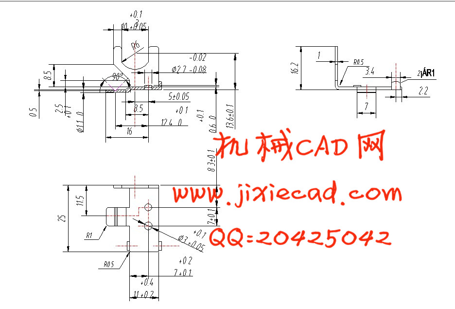
【摘要】:本课题是传真机左支架级进模具设计,通过冲裁件的工艺分析,确定零件能否进行冲裁,并明确在冲裁工艺及模具设计中主要解决的问题或难点所在。传真机左支架级进模模具包含冲孔和落料两个基本工艺步骤,其中冲孔包括三个工步,落料一个工步。由于该零件大批量生产,因此采用级进冲裁模,这样生产效率高,操作简便。该零件材料厚度较薄,尺寸小,呈圆形,因此采用直排样。为了便于操作和保证零件的精度,宜采用送料机和导正销配合定距,导料板导向的定位方式。考虑零件厚度较薄,采用弹性卸料方式,为了便于操作,提高生产率,冲件和废料采用由凸模直接从凹模洞口推下的下出件方式,由于零件厚度薄,冲裁间隙很小,级进模模具的定位精度要求较高,因此采用四导柱模架。凸凹模通过配合加工来满足凸凹模之间的精度要求。该模具的设计过程:先通过工艺分析确定了工件的排样图(其中包含:工艺步骤的划分,条料的定距方式,凸凹模的形状等),通过排样图确定凸凹模的尺寸,通过AUTOCAD绘制出凸凹模的工程图。
【关键词】:级进模;排样;冲孔;落料。
【Abstract】: This topic is the design of progressive die for the motor rotor core, by blanking technology analysis, determine if the part for punching, and specifically in punching technology and die design of the main problems or difficulties is located. Progressive die for the motor rotor core contains two basic punches and blanking process steps, which punches including three sequences, blanking a step. Due to the mass production of parts, so using progressive die, high production efficiency, easy operation. The part material thickness of a thin, small, round, with direct layout. For ease of operation and ensure the accuracy of parts, the use of side edge and pilot pin combined with distance, guiding plate oriented positioning. Consider part thickness thin, flexible discharge strategies, in order to facilitate operations, increase productivity, stamping and scrap used directly by a punch from the die hole pushed out of the way under, because the part thickness of thin, blanking clearance is very small, requiring high positioning accuracy of progressive die, so four-pillar. Punch and die through combined with processing to meet the accuracy requirements between the punch and die. The die of design process: first by technology analysis determine has workpiece of row sample figure (which contains: technology steps of Division, section material of will from way, punch die of shape,), by row sample figure determine punch die of size, by AUTOCAD draws out punch die of engineering figure, then application draws out die the part of three dimensional model, in accordance with the requirements with on die the parts for Assembly.
【Key words】: Progressive die; layout; punching; blanking.
目 录
前 言 1
1 零件介绍 4
2 零件的工艺性分析 4
2.1 结构形状 4
2.2 尺寸精度 5
2.3 材料 5
3 确定冲裁工艺方案 5
3.1 冲裁工艺方案 6
3.2 冲裁工艺方案分析 7
3.3 级进模具方案研究 7
4 确定模具总体结构方案 8
4.1 模具类型 9
4.2 操作与定位方式 9
4.3 卸料与出件方式 9
4.4 模架类型及精度 9
5 工艺与设计计算 9
5.1 排样 9
5.1.1 冲裁排样 9
5.1.2 搭边值的确定 10
5.1.3 材料的利用率 11
5.2 计算冲压力与压力中心,初选压力机 12
5.2.1 冲裁力的计算 12
5.2.2 辅助力的计算 12
5.2.3 压力机公称压力的选取 13
5.2.4 压力中心的确定 13
5.3 计算凸、凹模刃口尺寸及公差 14
5.3.1 凸、凹模刃口尺寸计算原则 14
5.3.2 凸、凹模刃口尺寸的计算方法 14
5.3.3 凸、凹模刃口尺寸计算 14
6 冲裁模具主要部件和零件的设计与选用 16
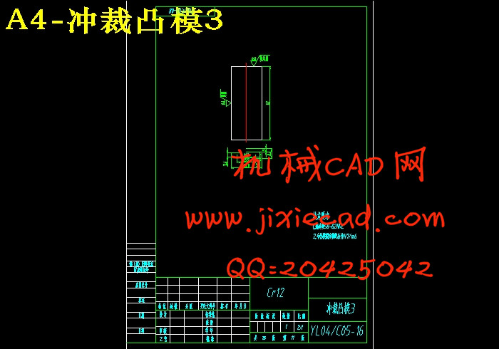
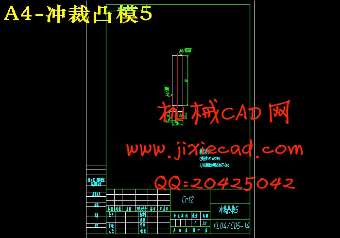
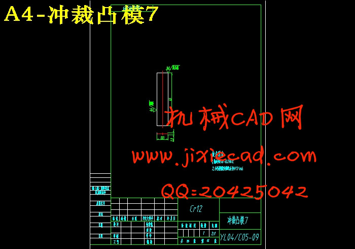
6.1.1 凸模的结构设计 16
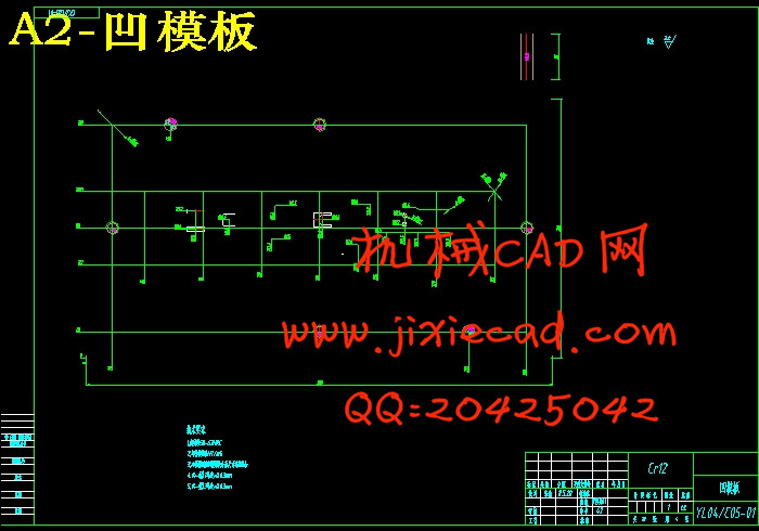
6.1.2 凹模的结构设计 19
6.2 定位零件结构设计 21
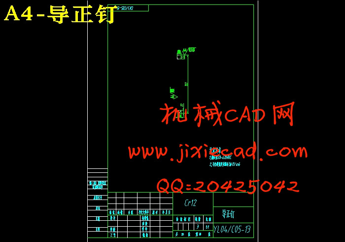
6.2.1 导正销 21
6.2.2 导料板和承料板 21
6.2.3 侧刃和侧刃挡块 22
6.3 卸料及压料零件结构设计 23
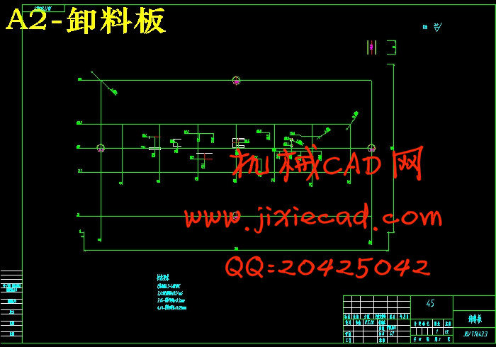
6.3.1 卸料板 23
6.3.2 卸料螺钉及弹簧 24
6.4 支撑固定零件 26
6.4.1 上、下模座 26
6.4.2 销钉 281 零件介绍 4
2 零件的工艺性分析 4
2.1 结构形状 4
2.2 尺寸精度 5
2.3 材料 5
3 确定冲裁工艺方案 5
3.1 冲裁工艺方案 6
3.2 冲裁工艺方案分析 7
3.3 级进模具方案研究 7
4 确定模具总体结构方案 8
4.1 模具类型 9
4.2 操作与定位方式 9
4.3 卸料与出件方式 9
4.4 模架类型及精度 9
5 工艺与设计计算 9
5.1 排样 9
5.1.1 冲裁排样 9
5.1.2 搭边值的确定 10
5.1.3 材料的利用率 11
5.2 计算冲压力与压力中心,初选压力机 12
5.2.1 冲裁力的计算 12
5.2.2 辅助力的计算 12
5.2.3 压力机公称压力的选取 13
5.2.4 压力中心的确定 13
5.3 计算凸、凹模刃口尺寸及公差 14
5.3.1 凸、凹模刃口尺寸计算原则 14
5.3.2 凸、凹模刃口尺寸的计算方法 14
5.3.3 凸、凹模刃口尺寸计算 14
6 冲裁模具主要部件和零件的设计与选用 16
6.1.1 凸模的结构设计 16
6.1.2 凹模的结构设计 19
6.2 定位零件结构设计 21
6.2.1 导正销 21
6.2.2 导料板和承料板 21
6.2.3 侧刃和侧刃挡块 22
6.3 卸料及压料零件结构设计 23
6.3.1 卸料板 23
6.3.2 卸料螺钉及弹簧 24
6.4 支撑固定零件 26
6.4.1 上、下模座 26
6.4.3 模柄 28
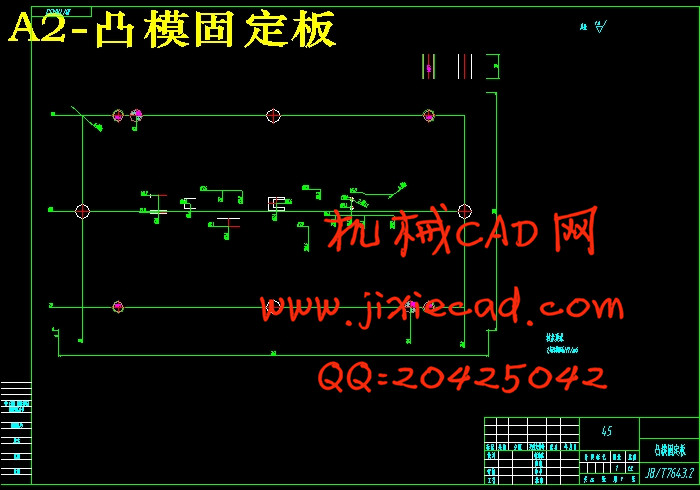
6.4.4 凸模固定板 28
6.4.5 卡环 29
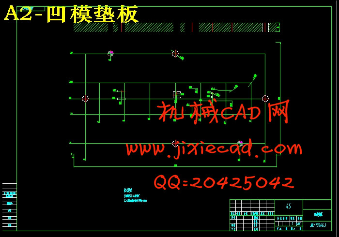
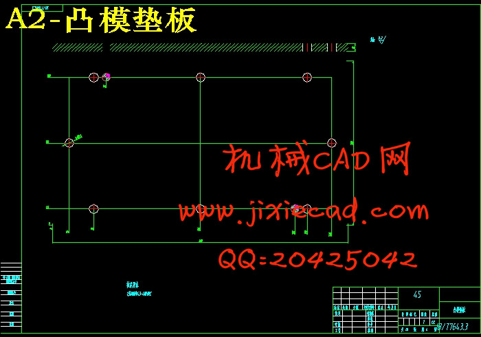
6.4.6 垫板 29
7 模具装配 30
7.1 上模装配 30
7.2 下模装配 32
7.3 模具总装 33
8 确定模具主要零件加工工艺过程 35
8.1 落料凸模加工工艺过程 35
8.2 中间孔凸模加工工艺过程 36
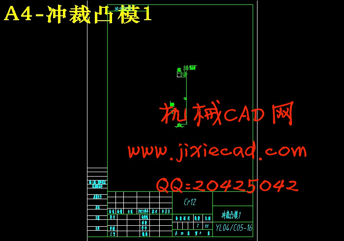
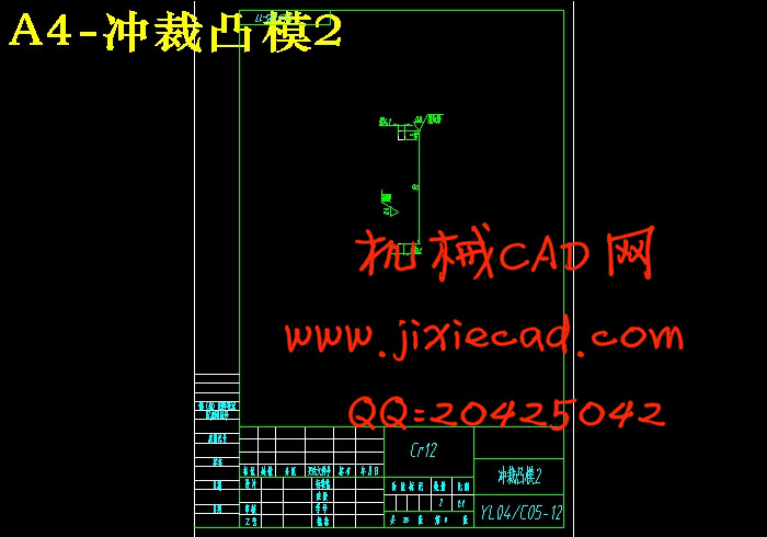
8.3 冲孔凸模加工工艺过程 36
8.4 切口槽孔凸模加工工艺过程 37
8.5凸模固定板加工工艺过程 37
8.6 凹模加工工艺过程 38
9 论文小结 39
参考文献 40
致谢 41