
设计简介
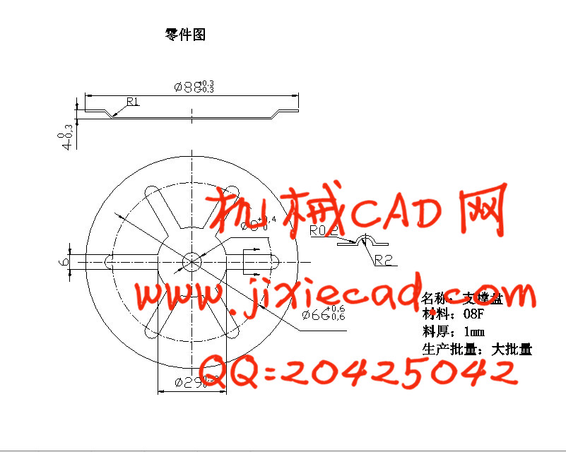
支撑盘冲压模设计
摘要:本设计题目为支撑盘冲压模设计,体现了盘类冲压零件的设计要求、内容及方向。有一定的设计意义,通过对该零件模具的设计,进一步加强了设计者冲压模设计的基础知识,为设计更复杂的冲压模具做好铺垫和吸取了更深刻的经验。
本设计运用冲压成型工艺及模具设计的基础知识,首先对零件进行工艺性分析,以确定冲压工序,然后计算零件的体积,便于选取合适的压力机,最后分析了零件的特征,确定模具的设计参数、设计要点及卸料装置的选取。
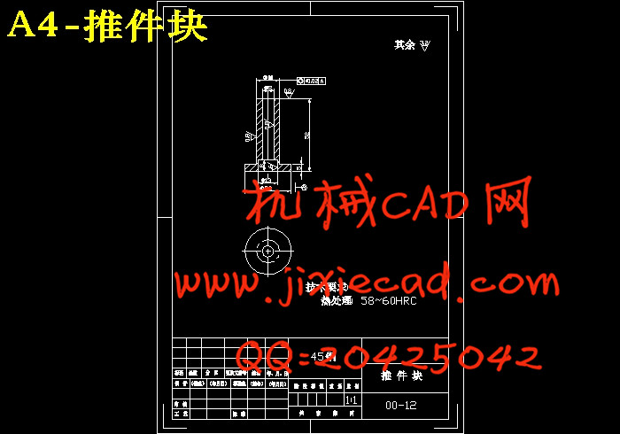
本冲压件的外缘和内孔均为圆形,所以在设计模具结构时,应考虑内孔与外缘的相对位置精度。又由于零件需要拉深,所以复合模是首选,其工序即为:落料、拉深、冲孔。模具的设计中,设计推件装置是关键,结合本副模具及零件的特点,刚性推件装置是比较合适的选择。
关键词:冲压模 复合模 推件装置
Disk die design
Abstract:The requirement ,content and direction of the design of the disk stamp parts are embodied on this pressing die design of the stamp parts of dam disk. The designer’s foundation knowledge of the stamp mould design is reinforced and is able to design more complex stamp mould through the design.
Through the foundation knowledge, firstly, the processibility of the part is analyzed to determine the process of the stamp. Secondly, the volume of the part is computed to choose the pressing machine. Lastly the character of the part is analyzed to determine the mould design parameter and design point and choose the shedding mechanism.
The pressworked part`s outer edge and internal hole are all circular.So when design the mold structure ,should consider the precision of relative position of the hole and the outflow boundary. Also because the part should be drawed, so,the compound die is the first choice.Its working procedure is:blanking、drawing、punched hole.In the mold design,the design of the equipment of pushing part is the key.Combing the characteristic of this mold and the part,the rigidity pushing equipment is a comparatively appropriate choice.
Keywords:Pressing die Compound die Pushing equipment
目 录
1 绪 论 1
1.1国内模具的现状和发展趋势 1
1.1.1国内模具的现状 1
1.1.2国内模具的发展趋势 3
1.2国外模具的现状和发展趋势 3
1.3支撑盘件模具设计与制造概述 4
1.3.1支撑盘模具设计的思路 4
1.3.2支撑盘模具设计的进度 4
2 支撑盘冲压成形工艺分析 5
2.1 制件结构工艺性分析: 5
2.2毛胚尺寸的确定: 6
2.3确定拉深主要工艺参数 7
2.4 冲压工艺方案的确定 7
2.5 确定排样方式及计算材料利用率 8
2.6 计算各工序冲压力和初选压力机吨位 9
3 模具的结构设计 12
3.1模具工作部分尺寸计算 12
3.1.1落料模尺寸 12
3.1.2拉深模尺寸 13
3.1.3 冲孔模尺寸 16
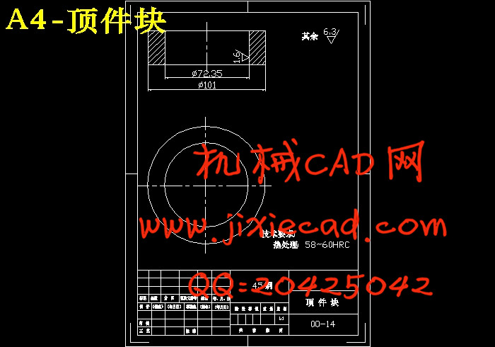
3.2 主要成形零部件结构设计 17
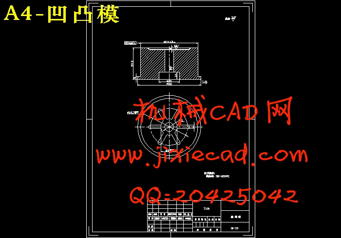
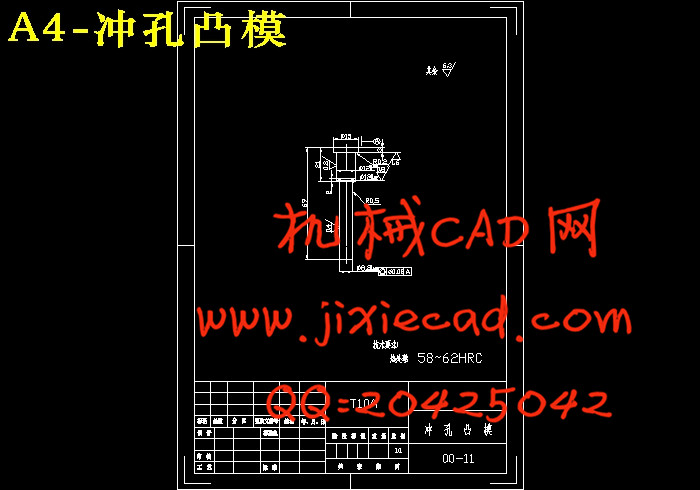
3.2.1凸凹模 拉深凹模 冲孔凸模 17
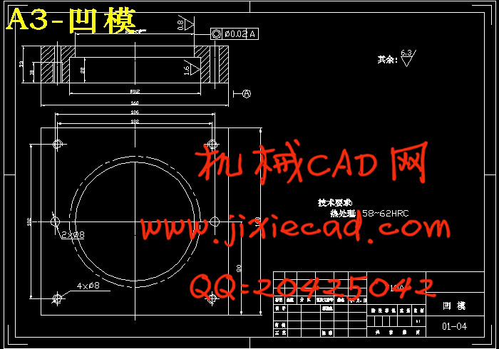
3.2.2凹模设计 19
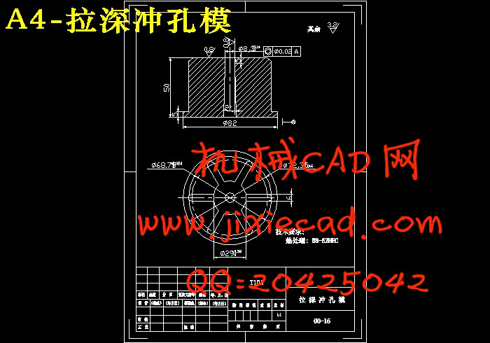
3.2.3拉深冲孔模设计 19
3.2.4 校核压力机冲孔凸模 20
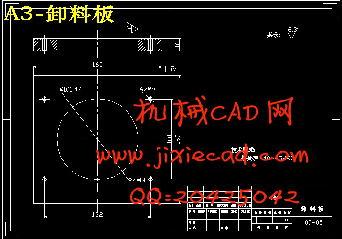
3.3 定位零部件以及卸料方式设计 21
3.4 模架 连接固定零件的选取 22
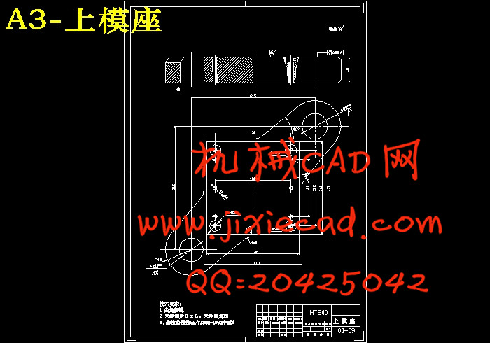
3.4.1上模座的选取 23
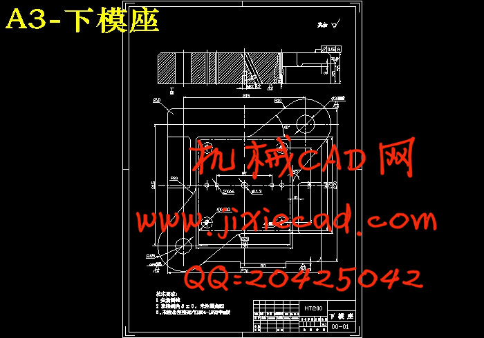
3.4.2下模座的选取 23
3.4.3导向零件的选取 23
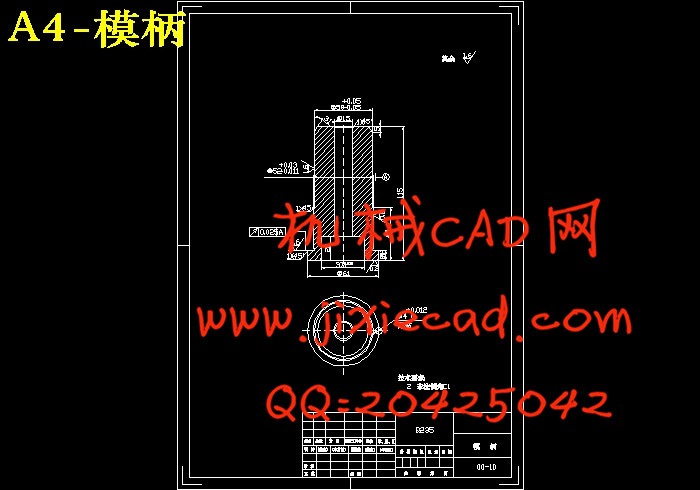
3.4.4模柄的选取 24
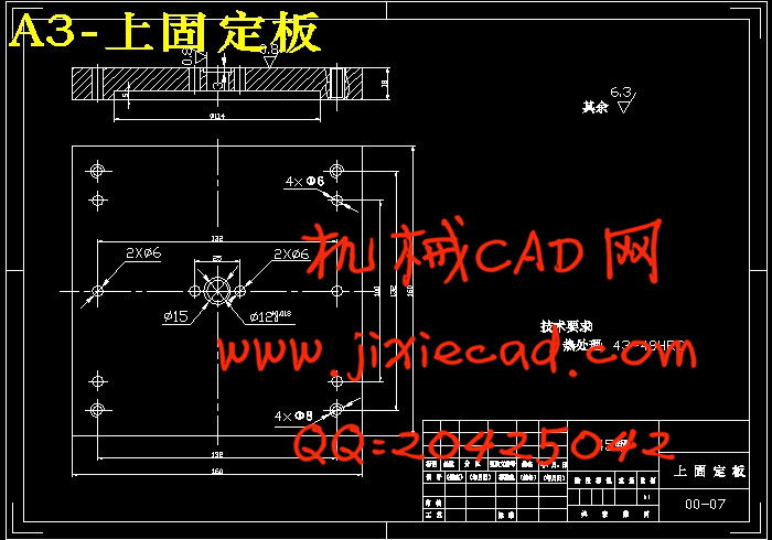
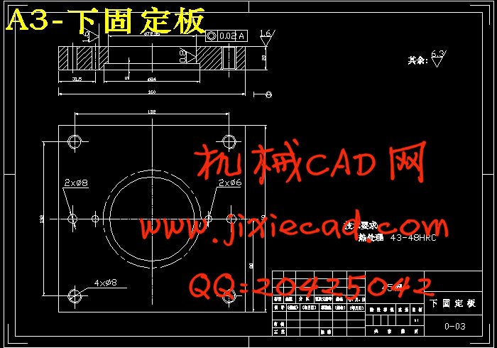
3.4.5固定板的选取 24
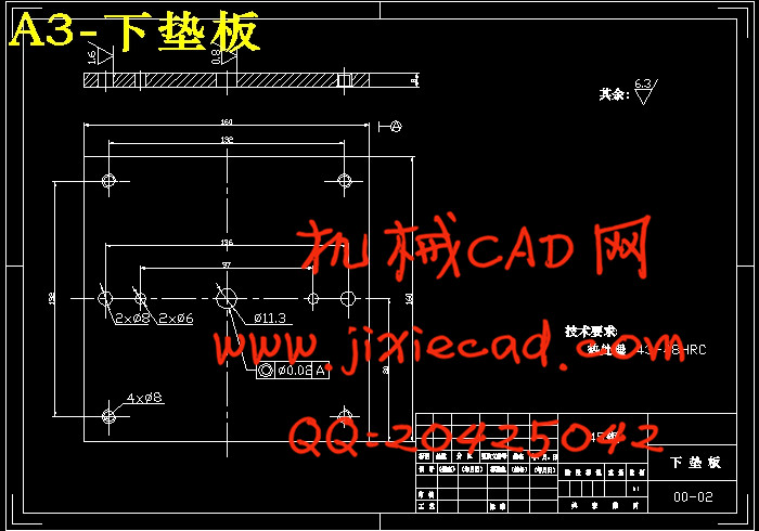
3.4.6垫板的选取 24
3.4.7螺钉和销钉的选取 24
4典型成形零部件的加工 25
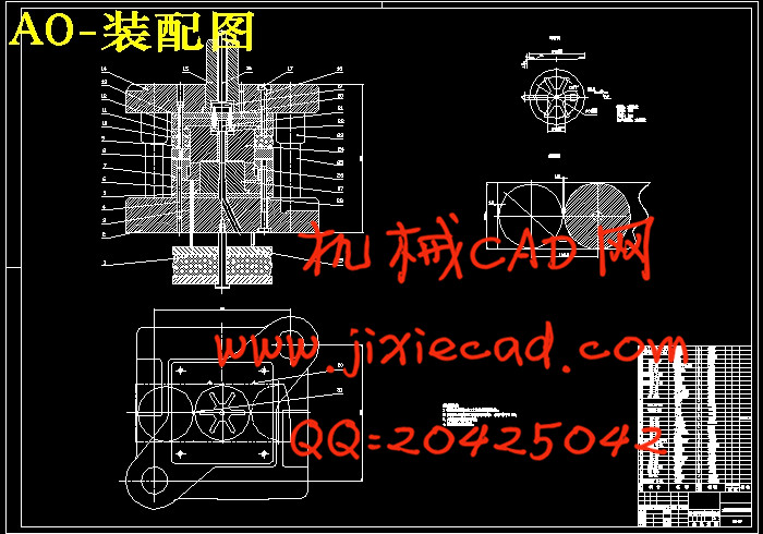
5 模具总装图 27
6压力机校核 29
7 结束语 30
致 谢 31
参考文献 32
摘要:本设计题目为支撑盘冲压模设计,体现了盘类冲压零件的设计要求、内容及方向。有一定的设计意义,通过对该零件模具的设计,进一步加强了设计者冲压模设计的基础知识,为设计更复杂的冲压模具做好铺垫和吸取了更深刻的经验。
本设计运用冲压成型工艺及模具设计的基础知识,首先对零件进行工艺性分析,以确定冲压工序,然后计算零件的体积,便于选取合适的压力机,最后分析了零件的特征,确定模具的设计参数、设计要点及卸料装置的选取。
本冲压件的外缘和内孔均为圆形,所以在设计模具结构时,应考虑内孔与外缘的相对位置精度。又由于零件需要拉深,所以复合模是首选,其工序即为:落料、拉深、冲孔。模具的设计中,设计推件装置是关键,结合本副模具及零件的特点,刚性推件装置是比较合适的选择。
关键词:冲压模 复合模 推件装置
Disk die design
Abstract:The requirement ,content and direction of the design of the disk stamp parts are embodied on this pressing die design of the stamp parts of dam disk. The designer’s foundation knowledge of the stamp mould design is reinforced and is able to design more complex stamp mould through the design.
Through the foundation knowledge, firstly, the processibility of the part is analyzed to determine the process of the stamp. Secondly, the volume of the part is computed to choose the pressing machine. Lastly the character of the part is analyzed to determine the mould design parameter and design point and choose the shedding mechanism.
The pressworked part`s outer edge and internal hole are all circular.So when design the mold structure ,should consider the precision of relative position of the hole and the outflow boundary. Also because the part should be drawed, so,the compound die is the first choice.Its working procedure is:blanking、drawing、punched hole.In the mold design,the design of the equipment of pushing part is the key.Combing the characteristic of this mold and the part,the rigidity pushing equipment is a comparatively appropriate choice.
Keywords:Pressing die Compound die Pushing equipment
目 录
1 绪 论 1
1.1国内模具的现状和发展趋势 1
1.1.1国内模具的现状 1
1.1.2国内模具的发展趋势 3
1.2国外模具的现状和发展趋势 3
1.3支撑盘件模具设计与制造概述 4
1.3.1支撑盘模具设计的思路 4
1.3.2支撑盘模具设计的进度 4
2 支撑盘冲压成形工艺分析 5
2.1 制件结构工艺性分析: 5
2.2毛胚尺寸的确定: 6
2.3确定拉深主要工艺参数 7
2.4 冲压工艺方案的确定 7
2.5 确定排样方式及计算材料利用率 8
2.6 计算各工序冲压力和初选压力机吨位 9
3 模具的结构设计 12
3.1模具工作部分尺寸计算 12
3.1.1落料模尺寸 12
3.1.2拉深模尺寸 13
3.1.3 冲孔模尺寸 16
3.2 主要成形零部件结构设计 17
3.2.1凸凹模 拉深凹模 冲孔凸模 17
3.2.2凹模设计 19
3.2.3拉深冲孔模设计 19
3.2.4 校核压力机冲孔凸模 20
3.3 定位零部件以及卸料方式设计 21
3.4 模架 连接固定零件的选取 22
3.4.1上模座的选取 23
3.4.2下模座的选取 23
3.4.3导向零件的选取 23
3.4.4模柄的选取 24
3.4.5固定板的选取 24
3.4.6垫板的选取 24
3.4.7螺钉和销钉的选取 24
4典型成形零部件的加工 25
5 模具总装图 27
6压力机校核 29
7 结束语 30
致 谢 31
参考文献 32