设计简介
摘要
此次设计任务是对3L-10/8空气压缩机曲轴零件的机械加工工艺、夹具的设计,在曲轴零件的加工工艺过程中轴与轴中心线之间要有位置要求, 以毛坯轴两端定位先加工两中心孔,以两端中心孔定位再粗、精加工各轴的表面,然后以粗、精后的两轴径定位钻螺纹、铣键槽和铣曲拐端面,采用专用夹具加工两斜油孔,最后粗、精磨各轴。
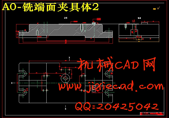
在夹具的设计过程中,主要以V形块和支承板来定位,靠直压板和弹簧来夹紧,钻拐径两孔应采用长型快换钻套,在钻拐径倾斜
关键词 曲轴,加工工艺,夹具设计。
ABSTRACT
This graduation project duty is to the 3L-10/8 air compressor crank components machine-finishing craft, the jig design, between the crank components processing technological process middle axle and the axle must have the position request ,processes two center bores first by the semifinished materials axis both sides localization ,by both sides center bore localization again thick, precision work various axes surface.Then after thick, the essence two axle diameter localization drills the thread, the keyseat and the mill crank end surface.,uses the unit clamp to process two slanting oil holes, finally thick, correct grinding various axes.
In the jig design process, mainly locates by V shape block and the support plate, depends on the straight clamp and the spring clamps, drills turns diameter two to be supposed to use long trades quickly drills the wrap, when drills turns the diameter incline hole uses the plane incline the jig body, when drills turns the diameter incline hole uses is the horizontal-type drilling machine, when face milling 2 V shape blocks and the milling cutter cannot interfere ,therefore V shape block altitude must reduce, the jig design must be convenient, be simple.
Key words crank, processing craft, jig design.
目 录
摘 要 I
ABSTRACT I
1 绪 论 1
2 零件分析 2
2.1零件的作用 2
2.2零件的工艺分析 2
2.3零件加工的主要问题和工艺过程设计分析 2
3 工艺规程设计 5
3.1确定毛坯的制造形式 5
3.2基面的选择 5
3.2.1 粗基准选择 5
3.2.2 精基准的选择 5
3.3制定工艺路线 5
3.4机械加工余量、工序尺寸及毛坯尺寸的确定 7
3.5 确定切削用量及基本工时 11
3.6 时间定额计算及生产安排 31
4 专用夹具设计 40
4.1加工曲拐上端面油孔夹具设计 40
4.1.1定位基准的选择 40
4.1.2切削力的计算与夹紧力分析 40
4.1.3夹紧元件及动力装置确定 41
4.1.4钻套、衬套及夹具体设计 42
4.1.5夹具精度分析 44
4.2加工曲拐上侧面油孔夹具设计 45
4.2.1定位基准的选择 45
4.2.2切削力的计算与夹紧力分析 45
4.2.3夹紧元件及动力装置确定 46
4.2.4钻套、衬套及夹具体设计 47
4.2.5夹具精度分析 48
4.3铣曲拐端面夹具设计 49
4.3.1定位基准的选择 49
4.3.2定位元件的设计 49
4.3.3铣削力与夹紧力计算 50
4.3.4对刀块和塞尺设计 51
4 结 论 53
参考文献 54
致 谢 55


