设计简介
摘 要
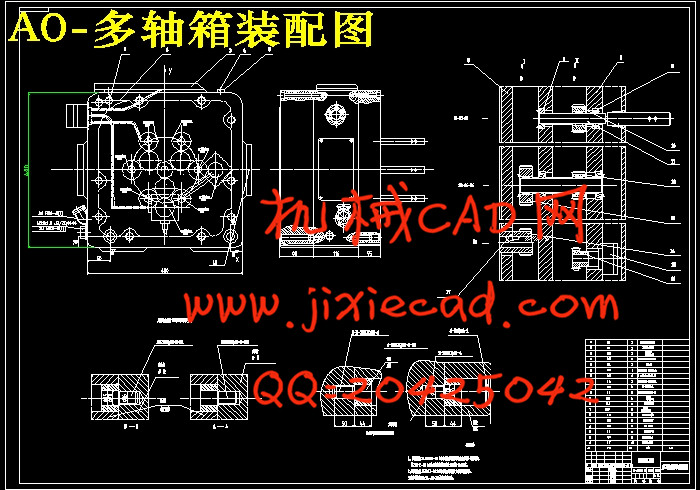
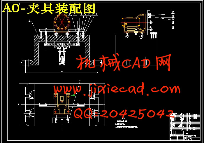
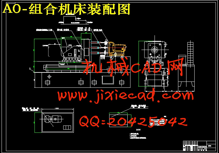
根据设计任务书的要求,本设计说明书针对壳体机床的设计及专用夹具设计进行说明。要内容包括组合机床工艺方案的制定、组合机床配置型式的选择、组合机床总体设计以及轴箱设计。全文要包括组合钻床的总体设计和轴箱设计两部分。机床总体设计要是在选定工艺方案并确定机床配置形式、结构方案基础上确定“三图一卡”, 主轴箱设计根据“三图一卡”,整理编绘出主轴箱原始依据图,重点分析传动系统,经过各种方案的比较,最后确定最优方案。此外,为了提高劳动生产率,降低劳动强度,保证加工质量,需设计专用夹具。
关键词:主轴箱;组合机床;夹具
Abstract
According to the requirements of the mission design, design for wallboard machine and special fixture for the design specification is described. The main contents include aggregate machine-tool craft plan formulation, combined machine tool configuration choice, aggregate machine-tool system design and main shaft case design.The full text mainly includes overall design and main shaft box combination milling machine design two parts. The overall design of machine tool is mainly in the selected process and determine the basis of machine tool configuration, structure scheme to determine the "three charts and a card", the headstock design according to "three charts and a card", reorganizes the compilation to leave the headstock primitive basis chart, the key analysis transmission system, through the comparison of various schemes, and finally to determine the optimal scheme. In addition, in order to improve labor productivity, reduce labor intensity, guaranteed the processing quality, need to design special jig.
Keywords: spindle box; modular machine tool; fixture
目 录
摘 要 IV
Abstract V
1 绪 论 1
1.1 毕业设计的目的 1
1.2 组合机床的特点 1
1.3 组合机床的发展前景 2
1.3.1 组合机床产品结构的变化 2
1.3.2 组合机床的快速转变 2
1.3.3 组合机床技术装备现状与发展趋势 2
1.3.4 组合机床行业的发展思考 4
2 零件的分析 6
2.1 零件的结构特点 6
2.2零件的结构特点及要求 6
2.3 零件的生产批量与机床的使用条件 6
2.4 确定组合机床的配置形式和结构方案 7
2.5 确定切削用量及选择刀具 8
2.5.1确定工序间余量 8
2.5.2选择切削用量 8
2.5.3确定切削力、切削扭矩、切削功率 8
2.5.4选择刀具结构 9
3 钻孔组合机床总设计“三图一卡”的编制 10
3.1 被加工零件工序图 10
3.2 加工示意图 11
3.3机床联系尺寸图 14
3.4生产率计算卡 17
4 主轴箱的设计 19
4.1 主轴箱的设计 19
4.1.1绘制主轴箱设计原始依据图 19
4.1.2齿轮模数选择 20
4.1.3主轴箱的传动设计 20
4.1.4绘制传动系统图 22
4.2 传动轴的直径估算 23
4.2.1 确定各轴转速 23
4.2.2传动轴直径的估算:确定各轴最小直径 23
4.2.3 键的选择 24
4.3 传动轴的校核 24
4.3.1 传动轴的校核 24
4.3.2 键的校核 25
4.4 各变速组齿轮模数的确定和校核 25
4.4.1 齿轮模数的确定 25
4.4.2 齿宽的确定 27
4.4.3 齿轮结构的设计 28
4.5 齿轮校验 28
4.5.1 校核a变速组齿轮 28
4.5.2 校核b变速组齿轮 29
4.5.3 校核c变速组齿轮 30
4.6 轴承的选用与校核 31
4.6.1 各轴轴承的选用 31
4.6.2 各轴轴承的校核 31
4.7 轴组件设计 32
4.8 轴的基本尺寸确定 33
4.8.1 外径尺寸D 33
4.8.2 轴孔径d 33
4.8.3 轴悬伸量a 34
4.8.4 支撑跨距L 34
4.8.5 轴最佳跨距
4.9 轴刚度验算 36
4.9.1 轴前支撑转角的验算 36
4.9.2 轴前端位移的验算 37
5 钻孔夹具设计 39
5.1 研究原始质料 39
5.2 定位、夹紧方案的选择 39
5.3切削力及夹紧力的计算 39
5.4 误差分析与计算 40
5.5 夹具设计及操作的简要说明 41
结 论 42
致 谢 43
参考文献 44


