设计简介
摘 要
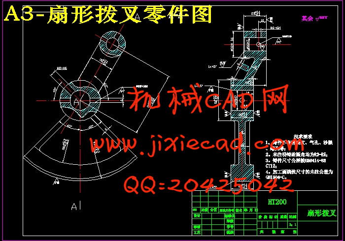
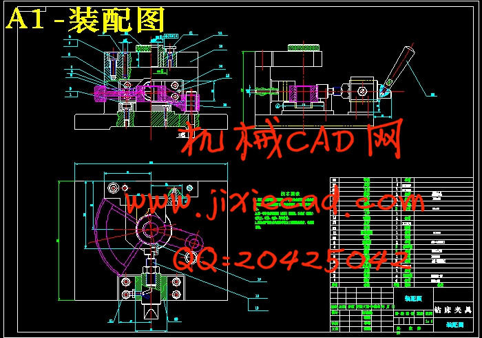
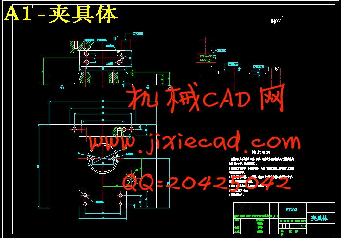
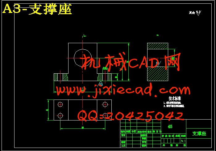
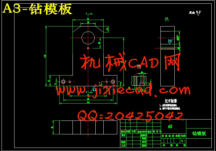
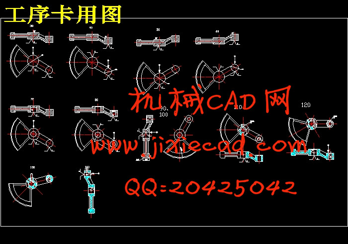
扇形拨叉零件加工工艺及钻床夹具设计是包括零件加工的工艺设计、工序设计以及专用夹具的设计三部分。在工艺设计中要首先对零件进行分析,了解零件的工艺再设计出毛坯的结构,并选择好零件的加工基准,设计出零件的工艺路线;接着对零件各个工步的工序进行尺寸计算,关键是决定出各个工序的工艺装备及切削用量;然后进行专用夹具的设计,选择设计出夹具的各个组成部件,如定位元件、夹紧元件、引导元件、夹具体与机床的连接部件以及其它部件;计算出夹具定位时产生的定位误差,分析夹具结构的合理性与不足之处,并在以后设计中注意改进。关键词:工艺,工序,切削用量,夹紧,定位,误差
Abstract
Fan-shaped fork parts processing and drilling parts machining fixture design including process design, process design, and special fixture design three parts. In the process of designing the parts to be the first analysis to understand the parts of the process re-design the structure of the blank, and select the machining datum good parts, the design process route parts; then the part of each step of the process to calculate the size of a key is to determine the technical equipment and cutting the amount of each process; then dedicated fixture design, select the design of the various components of the fixture, such as positioning elements, clamping elements, guiding element, clamp connections and machine parts and other components; positioning error generated when calculating the fixture, analytical rationality and inadequacies fixture structure and attention to improving the design in the future.Keywords: technology, processes, cutting the amount of clamping, positioning difference
目 录
摘 要 IIAbstract III
目 录 IV
第1章 序 言 1
第2章 零件的分析 2
2.1零件的形状 2
2.2零件的工艺分析 2
第3章 工艺规程设计 3
3.1 确定毛坯的制造形式 3
3.2 基面的选择 3
3.3 制定工艺路线 4
3.3.1 工艺路线方案一 4
3.3.2 工艺路线方案二 5
3.3.3 工艺方案的比较与分析 5
3.4 选择加工设备和工艺装备 6
3.4.1 机床选用 6
3.4.2 选择刀具 6
3.4.3 选择量具 6
3.5 机械加工余量、工序尺寸及毛坯尺寸的确定 7
3.6确定切削用量及基本工时 8
第4章 钻孔夹具设计 21
4.1 夹具的夹紧装置和定位装置 21
4.2 夹具的导向 22
4.3 定位方案分析与比较(列举了3种方案) 22
4.4钻孔与工件之间的切屑间隙 25
4.5 钻模板 26
4.6定位误差的分析 26
4.7 钻套、衬套、钻模板设计与选用 27
4.8确定夹具体结构和总体结构 28
4.9 夹具设计及操作的简要说明 29
总 结 30
致 谢 31
参 考 文 献 32


