设计简介
摘 要
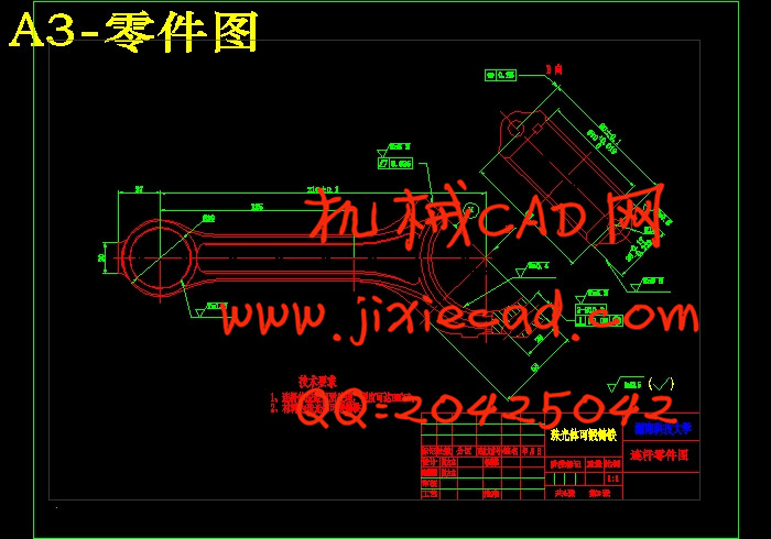
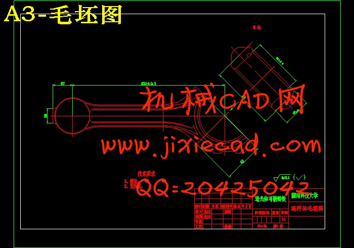
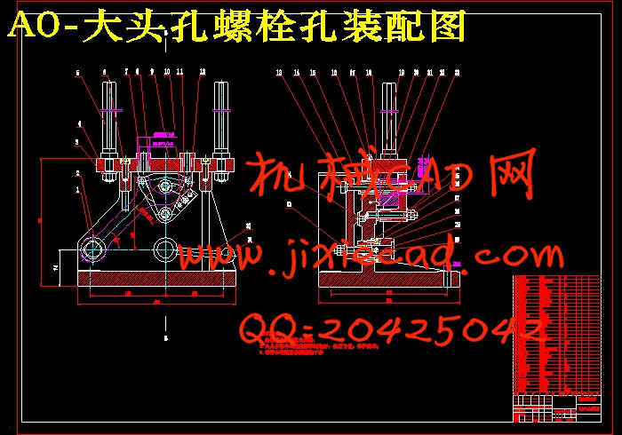
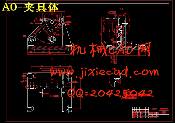
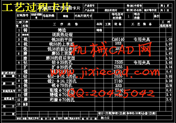
本文主要论述了柴油机连杆的加工工艺及其夹具设计。因为连杆是活塞式发动机和压缩机的主要零件之一,其大头孔与曲轴连接,小头孔通过活塞销与活塞连接,其作用是将活塞的气体压力传送给曲轴,又受曲轴驱动而带动活塞压缩汽缸中的气体。连杆承受的是冲击动载荷,因此要求连杆质量小,强度高。所以在安排工艺过程时,按照“先基准后一般”的加工原则。连杆的主要加工表面为大小头孔和两端面,较重要的加工表面为连杆体和盖的结合面及螺栓孔定位面。 在夹具设计方面也要针对连杆结构特点比较小,设计时应注意夹具体结构尺寸的大小等,最终就能达到零件的理想要求!
关键词: 连杆 变形 加工工艺 夹具设计
Keyword: Connecting rod Deformination Processing technology Design of clamping device
目 录
第一章 绪 论 1本文主要论述了柴油机连杆的加工工艺及其夹具设计。因为连杆是活塞式发动机和压缩机的主要零件之一,其大头孔与曲轴连接,小头孔通过活塞销与活塞连接,其作用是将活塞的气体压力传送给曲轴,又受曲轴驱动而带动活塞压缩汽缸中的气体。连杆承受的是冲击动载荷,因此要求连杆质量小,强度高。所以在安排工艺过程时,按照“先基准后一般”的加工原则。连杆的主要加工表面为大小头孔和两端面,较重要的加工表面为连杆体和盖的结合面及螺栓孔定位面。 在夹具设计方面也要针对连杆结构特点比较小,设计时应注意夹具体结构尺寸的大小等,最终就能达到零件的理想要求!
关键词: 连杆 变形 加工工艺 夹具设计
ABSTRACT
The diesel connecting rod treating handicraft the main body of a book has been discussed mainly and their grip design. Because of the connecting rod is one of dyadic engine of piston and main compression engine part, whose larger end hole and crank shaft link up , the small head hole links up by the wrist pin and the piston , whose effect is that the piston gas pressure is transmitted to the crank shaft , collect crank shaft gas in driving but setting a piston in motion to compress a cylinder. Being that the pole bears pounds a live load , request connecting rod mass is minor therefore , the intensity is high. Therefore when arranging procedure for, according to "first the criterion queen-like " treating principle. The connecting rod main part processes a surface being that head hole and both ends big or small are weak, more important faying face and bolt hole locating surface being the connecting rod body and cover treating outside. Also should be comparatively small specifically for connecting rod structure characteristic in the field of grip design , design that the size should pay attention to gripping the concrete structure dimension of the season waits, the ideal being therefore likely to reach a part ultimately demands!Keyword: Connecting rod Deformination Processing technology Design of clamping device
目 录
第二章 柴油机连杆的加工工艺 2
1.1 柴油机连杆的用途及其特点 2
1.1.1 柴油机连杆的主要技术要求 2
1.1.2 大、小头孔的尺寸精度、形状精度 3
1.1.3 大、小头孔轴心线在两个互相垂直方向的平行度 3
1.1.4 大、小头孔中心距 3
1.1.5 连杆大头孔两端面对大头孔中心线的垂直度 3
1.1.6 大、小头孔两端面的技术要求 3
1.1.7 螺栓孔的技术要求 4
1.2 连杆的的材料及毛坯制造 4
1.3 连杆的加工工艺过程 7
1.4 连杆的加工工艺过程分析 8
1.4.1 定位的选择 8
1.4.2 刀具的选择方案 14
1.4.3 切削用量的选择原则 15
1.4.4 加工阶段的划分和加工顺序的安排 16
1.4.5 确定合理的夹紧方法 17
1.4.6 连杆主要面的加工方法 18
1.4.7 连杆主要孔的加工方法 18
1.4.8 连杆体与连杆盖结合面的加工办法 19
1.4.9 连杆螺栓孔的加工方法 19
1.5 夹具使用 19
1.6 确定各工序的加工余量、计算工序尺寸及公差 19
1.6.1确定加工余量 19
1.6.2确定工序尺寸及其公差 20
1.7 各项加工数据的计算 21
1.8 冷却液的选择 28
1.9 连杆的检验 28
1.9.1 观察外表缺陷及目测表面粗糙度 29
1.9.2 检查主要表面的尺寸精度 29
1.9.3 检验主要表面的位置精度 29
1.9.4 连杆螺钉孔与结合面垂直度的检验 29
第三章 工装设计 30
2.1 铣削分面夹具设计(参考) 30
2.1.1 夹具的问题注意 30
2.1.2 夹具设计 30
2.2 螺栓孔孔夹具(本次设计的夹具) 32
2.2.1 夹具的注意问题 32
2.2.2 夹具设计 32
第四章 结论 36
参考文献 38
致谢 39


