设计简介
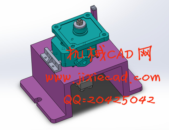
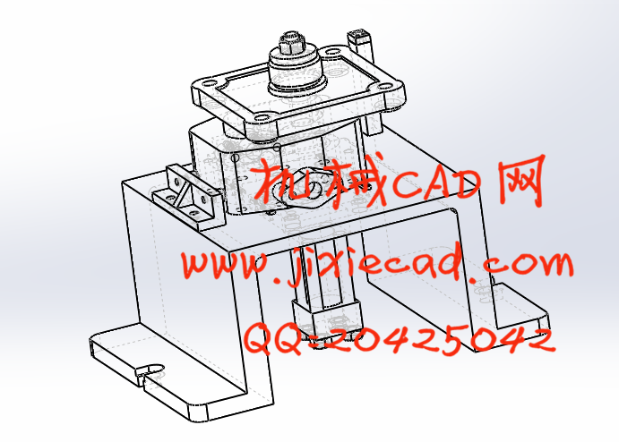
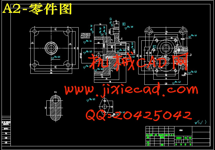
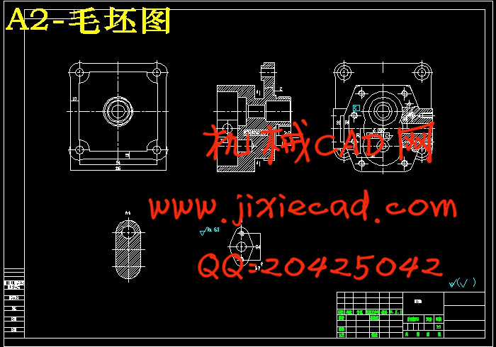
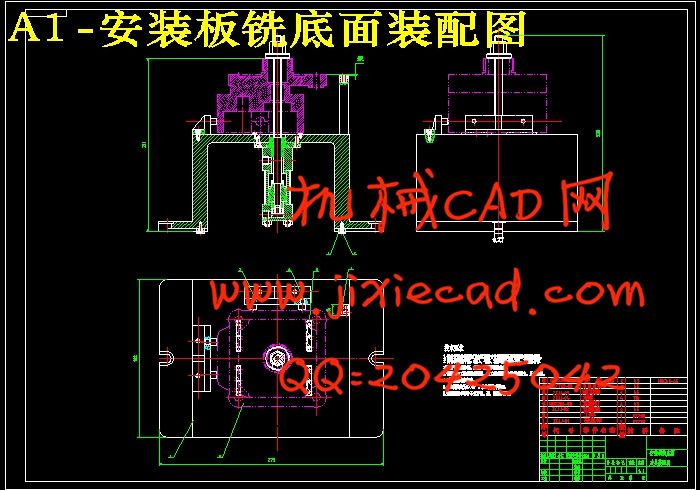
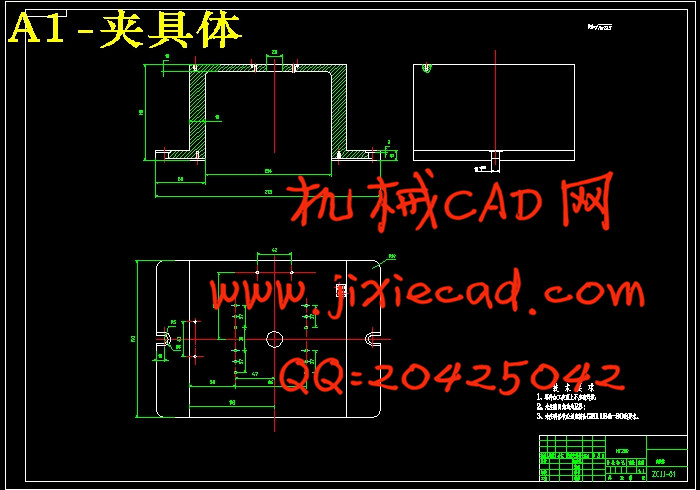
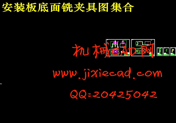
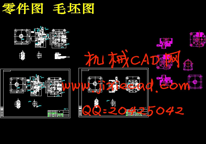
A型齿轮油泵泵体零件加工工艺及夹具设计是包括零件加工的工艺设计、工序设计以及专用夹具的设计三部分。在工艺设计中要首先对零件进行分析,了解零件的工艺再设计出毛坯的结构,并选择好零件的加工基准,设计出零件的工艺路线;接着对零件各个工步的工序进行尺寸计算,关键是决定出各个工序的工艺装备及切削用量;然后进行专用夹具的设计,选择设计出夹具的各个组成部件,如定位元件、夹紧元件、引导元件、夹具体与机床的连接部件以及其它部件;计算出夹具定位时产生的定位误差,分析夹具结构的合理性与不足之处,并在以后设计中注意改进。
关键词 工艺,工序,切削用量,夹紧,定位,误差
Abstract
Disc type parts processing technology and fixture design is the design of process design, including the parts processing process design and the three part special fixture. In the process of design should first of all parts to analyze, understand parts of the process and then design a blank structure, and choose the good parts of the machining datum, designs the process routes of the parts; then the parts each step process dimension calculation, the key is to determine the process equipment and cutting the amount of each working procedure design; then a special fixture, fixture for the various components of a design, such as the connecting part positioning device, clamping element, a guide element, clamp and the machine tool and other components; the positioning error caused calculate fixture when positioning, analysis of the rationality and deficiency of fixture structure, pay attention to improving and will design in.
Keywords process, process, cutting, clamping, positioning, error
目 录
第1章 绪 论 1
1.1 夹具设计目的与意义 1
1.2 专用夹具设计的国内外现状 2
1.2.1 国内专用技术应用及现状 2
1.2.2 专用工艺在国外的发展状况 3
1.3 专用夹具设计的发展趋势 4
第2章 专用夹具的设计 6
2.1 铣床专用夹具的主要类型 6
2.2 铣床专用夹具的设计要点 6
2.3 夹紧装置 7
2.4 专用夹具的基准选择 7
2.5 机床夹具的概述 8
2.5.1 机床夹具的种类 8
2.5.2 机床夹具的组成 8
2.6 铣床夹具的分类 9
2.7 铣削专用夹具的设计要点 9
2.8 铣床夹具的安装 9
2.9 工件的定位与误差分析 10
2.9.1 工件定位的基本原理 10
2.9.2 定位方法与定位元件 11
2.9.3 工件的误差分析 12
2.9.4 定位误差产生的原因 12
2.10 夹紧装置 13
2.10.1夹紧装置的组成 13
2.10.2 对夹紧装置的基本要求 13
2.10.3 夹紧力的确定 14
2.10.4 夹紧力大小计算 14
第3章 铣削安装板底面精加工工序专用夹具的设计 16
3.1 明确设计任务,了解零件加工工艺过程 16
3.1.1 熟悉工件零件图、本工序加工要求 16
3.1.2 熟悉零件加工工艺过程 16
3.2 确定定位方案 16
3.2.1 基准的选择 16
3.2.2 确定定位夹紧方案 17
3.2.3 定位元件的选择及设计 17
3.3 定位误差的计算与分析 18
3.4 计算切削力及实际所需的夹紧力 19
3.5 设计夹紧机构并验算机构所能产生的夹紧力 21
3.6 主要元件的设计与建模 22
3.7 对刀元件及夹具体 23
第4章 夹具图的绘制 24
4.1 工序图 24
4.2 夹具体零件图 24
4.3 绘制夹具装配总图 24
4.4 标注总图上的尺寸、公差与配合和技术条件 25
4.4.1 标注尺寸、公差与配合 25
4.4.2制订技术条件 25
4.5 三维装配图SOLIDWORKS建模 26
第5章 夹具工作精度分析 30
5.1 位置尺寸70 0.10 30
5.2平面度允差0.2mm 30
结论 31
致谢 32
参考文献 33
关键词 工艺,工序,切削用量,夹紧,定位,误差
Abstract
Disc type parts processing technology and fixture design is the design of process design, including the parts processing process design and the three part special fixture. In the process of design should first of all parts to analyze, understand parts of the process and then design a blank structure, and choose the good parts of the machining datum, designs the process routes of the parts; then the parts each step process dimension calculation, the key is to determine the process equipment and cutting the amount of each working procedure design; then a special fixture, fixture for the various components of a design, such as the connecting part positioning device, clamping element, a guide element, clamp and the machine tool and other components; the positioning error caused calculate fixture when positioning, analysis of the rationality and deficiency of fixture structure, pay attention to improving and will design in.
Keywords process, process, cutting, clamping, positioning, error
目 录
第1章 绪 论 1
1.1 夹具设计目的与意义 1
1.2 专用夹具设计的国内外现状 2
1.2.1 国内专用技术应用及现状 2
1.2.2 专用工艺在国外的发展状况 3
1.3 专用夹具设计的发展趋势 4
第2章 专用夹具的设计 6
2.1 铣床专用夹具的主要类型 6
2.2 铣床专用夹具的设计要点 6
2.3 夹紧装置 7
2.4 专用夹具的基准选择 7
2.5 机床夹具的概述 8
2.5.1 机床夹具的种类 8
2.5.2 机床夹具的组成 8
2.6 铣床夹具的分类 9
2.7 铣削专用夹具的设计要点 9
2.8 铣床夹具的安装 9
2.9 工件的定位与误差分析 10
2.9.1 工件定位的基本原理 10
2.9.2 定位方法与定位元件 11
2.9.3 工件的误差分析 12
2.9.4 定位误差产生的原因 12
2.10 夹紧装置 13
2.10.1夹紧装置的组成 13
2.10.2 对夹紧装置的基本要求 13
2.10.3 夹紧力的确定 14
2.10.4 夹紧力大小计算 14
第3章 铣削安装板底面精加工工序专用夹具的设计 16
3.1 明确设计任务,了解零件加工工艺过程 16
3.1.1 熟悉工件零件图、本工序加工要求 16
3.1.2 熟悉零件加工工艺过程 16
3.2 确定定位方案 16
3.2.1 基准的选择 16
3.2.2 确定定位夹紧方案 17
3.2.3 定位元件的选择及设计 17
3.3 定位误差的计算与分析 18
3.4 计算切削力及实际所需的夹紧力 19
3.5 设计夹紧机构并验算机构所能产生的夹紧力 21
3.6 主要元件的设计与建模 22
3.7 对刀元件及夹具体 23
第4章 夹具图的绘制 24
4.1 工序图 24
4.2 夹具体零件图 24
4.3 绘制夹具装配总图 24
4.4 标注总图上的尺寸、公差与配合和技术条件 25
4.4.1 标注尺寸、公差与配合 25
4.4.2制订技术条件 25
4.5 三维装配图SOLIDWORKS建模 26
第5章 夹具工作精度分析 30
5.1 位置尺寸70
5.2平面度允差0.2mm 30
结论 31
致谢 32
参考文献 33


