设计简介
摘 要
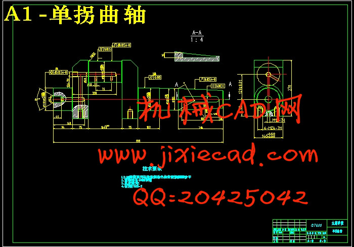
本文是对曲轴零件三维造型及零件的机械加工工艺路线的设计,并根据加工工序的要求完成对夹具的设计。三维造型主要表达了零件的造型过程,并可根据零件三维图样自动生成零件的数控加工程序。
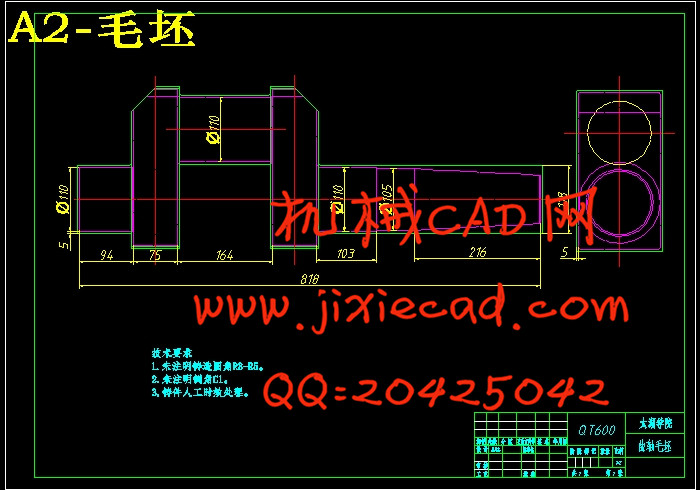
曲轴作为轴类零件,其主要加工表面是外圆及端面。其结构相对简单,加工时间少,加工成本较低,但零件的加工精度要求较高。按照机械加工工艺要求,需遵循先面后孔的原则,并且为了保证加工精度将孔与平面的加工明确划分成粗加工和精加工阶段。基准选择以外圆面作为粗基准,以两个中心孔作为精基准,确定了其加工的工艺路线和加工中所需要的各种工艺参数。
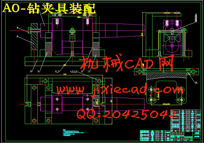
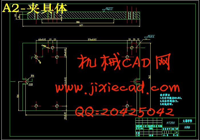
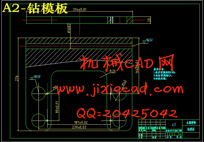
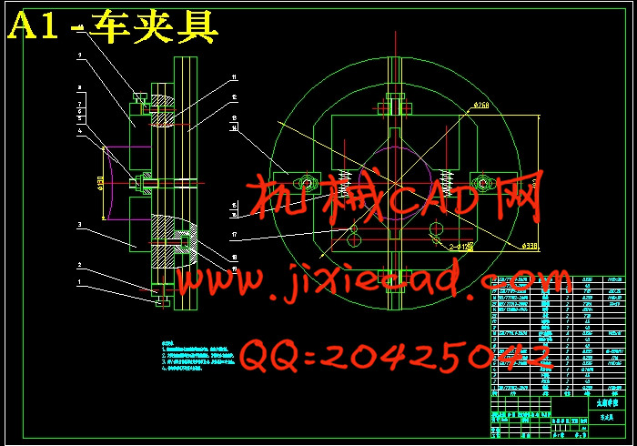
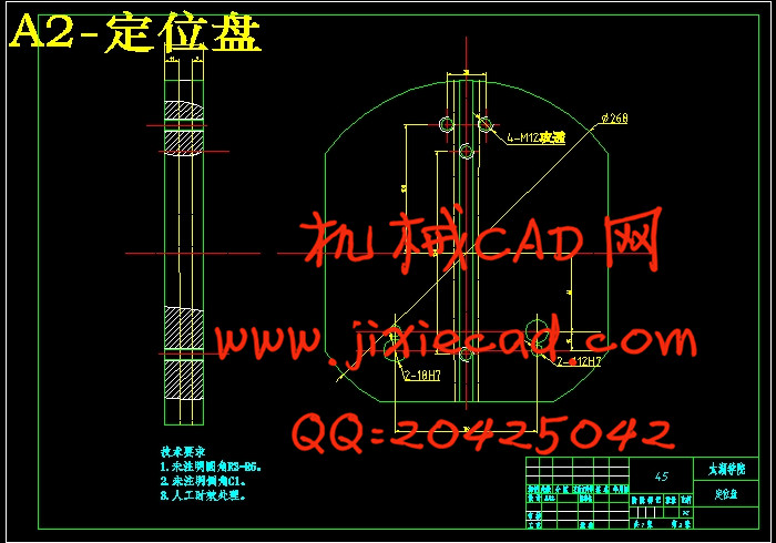
在零件的夹具设计中,主要是根据零件加工工序要求,分析应当限制的自由度的数量,进而根据零件的表面特征选定定位元件,再分析所选定位元件能否限定应限自由度。确定了定位元件后还需要选择夹紧元件,最后就是来完成专用夹具的结构设计。
关键词:曲轴;加工工艺;工序;专用夹具
Abstract
This paper is the design of line machining technology of the three dimension modeling and parts of Crankshaft parts. According to desire, the author designed the fixture of the work-piece. Three dimension modeling described the process of the work-piece. Then auto generated the computer program according to the modeling.
The Crankshaft components as a class of axis, its main processing surface are the plane and the cylindrical. According to the machine-finishing technological requirement, after following the first surface then the hole principle, and is clear about the hole and the plane processing divides the rough machining and the precision work stage guarantees the working accuracy. The datum choice takes the cylindrical surface by the support surface, takes the fine datum by the support two center holes, had determined in its processing's craft route and the processing needs each technological parameter.
In the designing of the fixture, selected the orientation units is the main work. And analyzed the restriction of the work-piece when the machining. Then selected the gripping components and decided the contracture of the fixture.
Key words: crankshaft; machining processing; workstage; special fixture
目 录
摘 要 III
ABSTRACT IV
目录 V
1 绪论 1
1.1本课题的研究内容和意义 1
1.2国内外的发展概况 1
1.3本课题应达到的要求 2
2 零件的造型 4
2.1 零件造型软件的介绍 4
2.2 零件造型的流程 4
3 零件的工艺分析 8
3.1 零件的工艺分析 8
3.2 零件的功用分析 8
3.2.1 轴类零件的功用 8
轴类零件的主要技术要求 8
轴类零件的材料、毛坯及热处理 9
4 零件工艺规程的设计 10
4.1 确定制造毛坯的方式 10
4.2 加工方法分析及确定 10
4.3 加工顺序的安排 10
4.4 定位基准的选择 10
4.4.1 选择定位基准的方法 10
4.4.2 轴类零件的定位基准与装夹方法 12
4.5 拟定加工零件的工艺路线 13
5 毛坯尺寸、工序尺寸和机械加工余量的确定 17
5.1 工序尺寸及公差的确定 17
5.2 设备及工艺装备的确定 20
5.3 切削用量及工时定额的确定 20
6 钻4-φ22孔专用夹具设计 26
6.1 指出加工过程中的问题 26
6.1.1 机床夹具的作用 26
6.1.2 钻床夹具的类型 26
6.1.3 钻夹具选择的原则 27
6.2 夹具的设计 27
6.2.1 定位基准的选择 27
6.2.2 定位方案的确定 28
6.2.3 定位元件的确定 28
6.2.4 切削力及夹紧力计算 28
6.2.5钻套、连接元件及钻模板的设计 29
6.2.6 夹具体的设计 30
6.2.7 夹具精度分析 30
6.2.8 夹具设计及操作的简要说明 30
7车曲轴轴颈专用夹具设计 31
7.1 问题的指出 31
7.2车夹具的选择与设计 31
7.3 夹具设计 31
7.3.1 选择定位基准 31
7.3.2 确定定位元件 31
7.3.3 夹紧装置的设计要求 32
7.3.4 夹具体的设计 32
7.3.5 夹具精度分析 33
7.3.6夹具设计及操作的简要说明 33
8 结论与展望 34
8.1结论 34
8.2不足之处及未来展望 34
毕业设计小结 35
致谢 36
参考文献 37


