设计简介
摘要
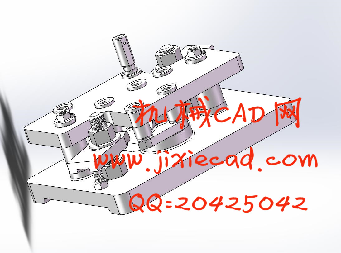
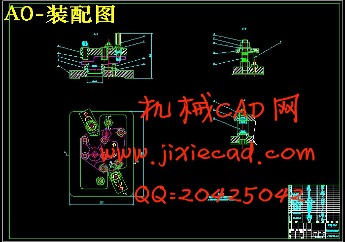
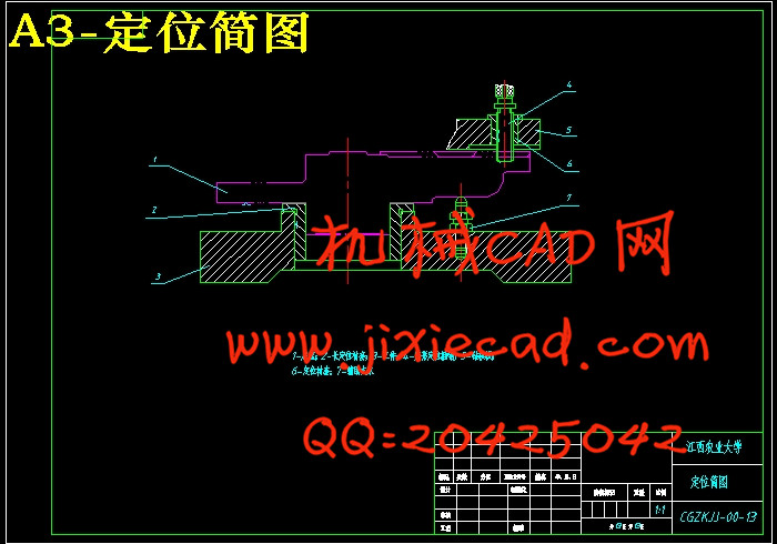
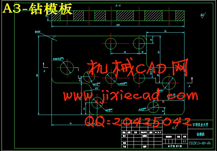
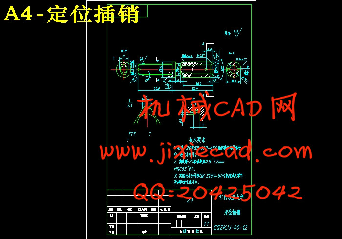
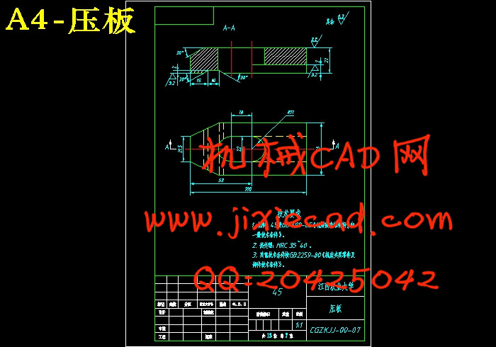
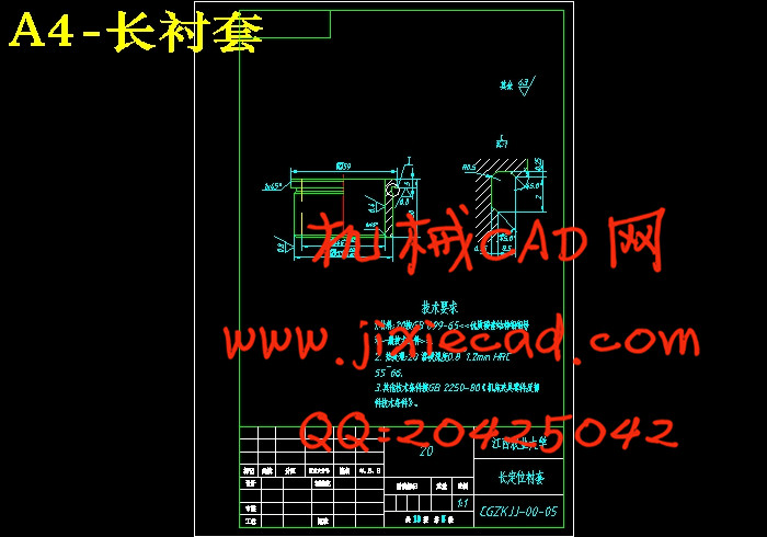
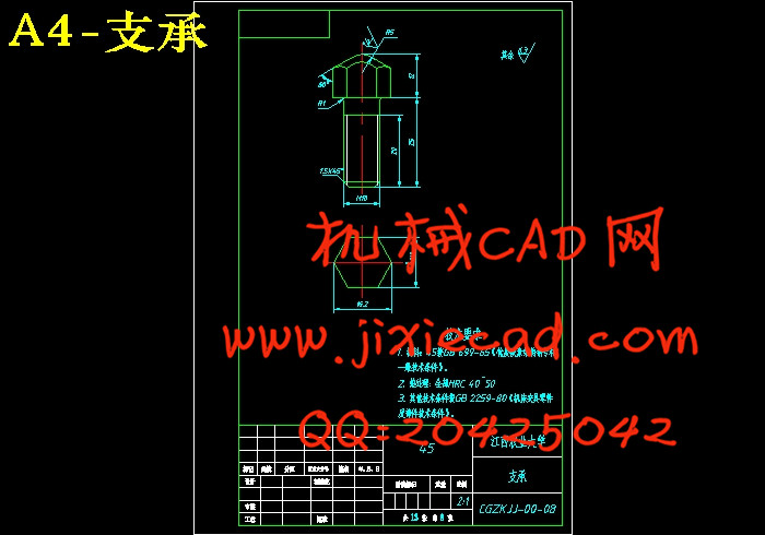
此次设计是对方向机侧盖零件的钻孔专用夹具设计,加工零件为铸件,具有体积小,零件复杂的特点。针对加工孔的工序选择“一孔一销”的定位方式,并以操作简单的手动螺旋夹紧方式夹紧,其机构设计简单,方便且能满足要求。 设计中选择的钻模板是盖板式钻模,这种钻模无夹具体,其定位元件和夹紧装置直接装在钻模板上。钻模板在工件上装夹,适合于工件上的小孔加工。夹具结构简单轻便,易清除切屑。该套夹具的定位元件主要有长定位衬套和定位插销,限制工件的五个自由度,完成对工件的定位。夹紧机构采用的是手动螺旋夹紧机构。其具有下列特点:结构简单、扩力比大、自锁性能好、行程不受限制、夹紧动作慢等。本套夹具的夹紧装置为两块可移动压板。通过螺栓夹紧移动压板,达到夹紧作用。
关键词:方向机侧盖;夹具设计;定位;夹紧
Abstract
This design is on the side cover steering drilling special fixture design parts,the processing components are a casting, with a small size, the characteristics of complex parts. Hole machining process for selecting "a hole and a selling" positioning of the way and simplicity of operator manual screw clamp way clampts organization design is simple, the convenience also can satisfy the request.The choice in the design of the drill template is a cover board type drill mode, this drill die without clip concrete, its orientation components and clamping device installed in drill template directly. Drilling templates in the jacket clip, suitable for the processing of small holes. Fixture simple structure compact, easy cleaning out scraps. This set of fixture positioning elements are mainly of locating long and positioning pin, limit the five degrees of freedom and the completion of the positioning of the workpiece. Clamping institutions use is manual spiral clamping institutions. It has the following characteristics: simple structure, expansion force than the big, good performance, lock schedule doesn't restricted, clamping slow, etc. This set of clamping fixture device is two pieces of mobile linking piece. Through the bolt clamping mobile linking piece, achieve clamping role.
Key words: steering box side cover; fixture design; orientation; clamping
目录
摘要 I
Abstract II
1 设计任务 1
1.1 设计题目 1
1.2 工件的加工工艺分析 2
1.3 钻床夹具的组成 2
1.4 钻床夹具特点的分析 2
2 工件的定位方案分析 4
2.1 工件的定位原理 4
2.2 具体定位方案分析 4
2.3 定位元件的选择 5
2.4 定位误差分析 5
2.4.1 位置度误差分析 6
2.4.2 偏转角度误差分析 6
2.4.3 竖轴心线的偏移误差分析 7
3 工件夹紧方案的分析 7
3.1 工件的夹紧原理 7
3.2 夹紧装置的确定 7
3.2.1 夹紧装置的组成和基本要求 7
3.2.2 具体的夹紧装置 8
3.3 夹紧力的确定 9
3.3.1 夹紧力的方向的确定 9
3.3.2 夹紧力的作用点的选择 9
3.3.3 夹紧力大小的估算 10
3.3.4 移动压板的确定 12
4 引导装置的确定 13
4.1 引导装置的作用 13
4.2 具体的引导装置 14
4.3 钻套与工件之间的距离计算 14
5 钻模板的确定 15
6 底座的确定 16
7 夹具操作过程及选取机床、刀具 17
参考文献 19
总结与致谢 20


