设计简介
摘 要
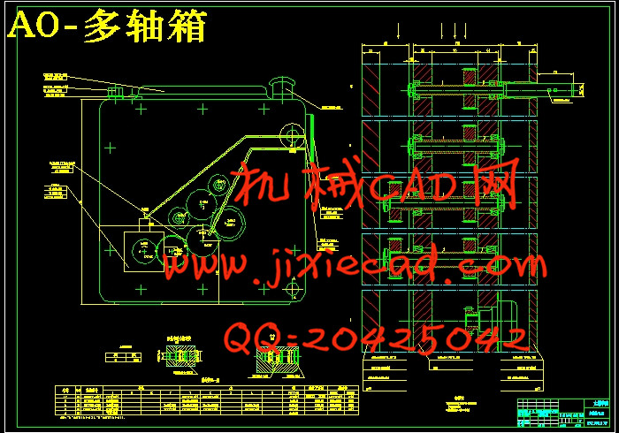
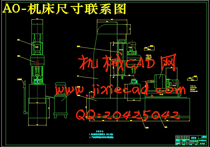
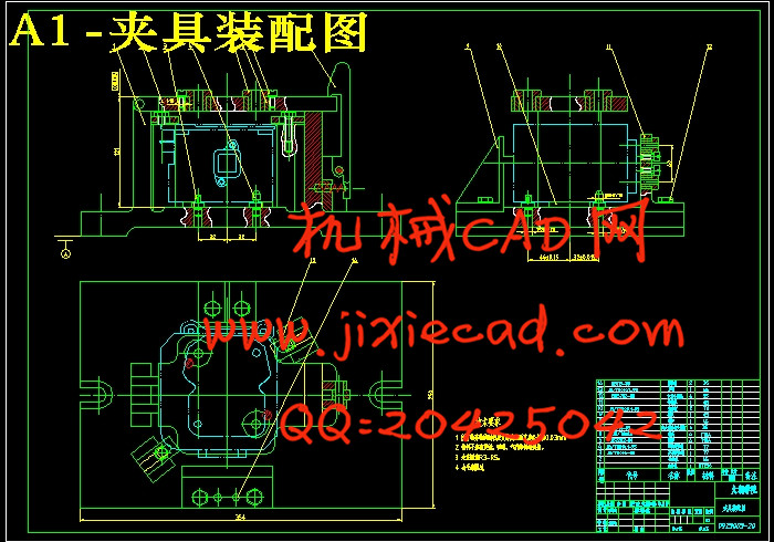
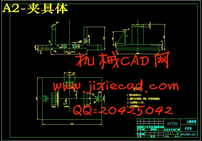
本课题是研究一台对缸头进行加工的两面精镗组合机床,主要是对组合机床的总体结构、夹具和多轴箱的设计。首先概括了组合机床的发展,阐述了组合机床的低成本、高效率、操作使用简单等优点。然后是机床夹具的设计,采用“一面两销”的定位方式,使定位更准确;通过误差分析,夹紧力计算等确定夹具的总体结构。其次是对组合机床的设计,关键是工艺方案的拟定,这大体决定组合机床的配置形式和使用性能,然后编制“三图一卡”。最后是多轴箱的设计,通过工件的尺寸和加工孔的位置计算出主轴箱的轮廓尺寸;根据扭矩的计算得出主轴和传动轴的直径;通过类比法确定齿轮的模数;通过“计算、作图和多次试凑”确定齿轮齿数和中间传动轴的位置。在总体设计过程中,首先通过计算所需功率选择动力箱,然后根据主轴的分布情况选用多轴箱;之后根据动力箱和加工行程图来选择液压滑台,再由液压滑台选用配套的多轴箱;再配合装料高度、滑台、侧底座相互位置等来确定中间底座的高度和长度。关键词:组合机床;精镗;缸头;多轴箱
Abstract
This topic is the study of a station on both sides of the cylinder head for processing fine boring combination machine, mainly on the overall structure of machine tool, fixtures, and multi-axle design. Firstly, this paper outlines the development of combined machine, explians its feature is low-cost, high efficiency, and with simple operation etc... Then tells the machine tool fixture design, the use of "locating a surface with two pins" positioning ways to make more accurate positioning; through error analysis, fixture clamping force calculation to determine the overall structure. Secondly, the design is a combination machine, the key is the program development process, which largely determines the form of combination machine configuration and performance, and the preparation of "the three charts card". Finally, the research is about multi-axle design, size and processing through the workpiece hole position calculated headstock outline dimensions; calculated according to the torque shaft and shaft diameter; determined by analogy gear modulus; through the "Calculation , mapping and repeated trial and error "OK gear and intermediate shaft position. In the overall design process, first select the required power by calculating the power box, and then choose the distribution of multi-spindle axle; after power box and processed according to the choice of hydraulic travel diagram slide, and then the hydraulic multi-slide supporting optional axle; together with loading height, slide, side stand each other to determine the location of the middle of the base of the height and length.Key words: Aombination machine; Boring; Cylinder head; Multi-spindle box
目 录
摘 要 III
Abstract IV
目录 IV
1 绪论 1
1.1本课题的研究内容和意义 1
1.2国内外的发展概况 1
1.3本课题应达到的要求 1
2 设计方案的确定 2
2.1工件的大小、形状和加工部分的特点 2
2.2生产率的影响 2
2.3经济性与可靠性 2
3专用夹具的设计 3
3.1夹具的功用与组成 3
3.2夹具的设计 3
3.2.1调研分析 3
3.2.2确定工件定位方式 3
3.2.3确定工件加紧方式 4
3.2.4必要的加工精度计算及分析 4
3.2.5夹紧力计算、分析 4
4 组合机床总体设计 6
4.1组合机床的组成 6
4.1.1组合机床的特点 6
4.1.2组合机床的工艺范围 6
4.1.3组合机床配置型式 6
4.1.4组合机床的设计步骤 7
4.2组合机床工艺方案的确定 7
4.2.1组合机床工艺方案的基本原则 7
4.2.2确定组合机床工艺方案应注意的问题 7
4.2.3工艺方案的拟订 8
4.2.4工序间余量的确定 8
4.2.5刀具结构的选择 9
4.3切削用量的确定 9
4.3.1组合机床切削用量选择的特点、方法及注意问题 9
4.3.2组合机床切削用量选择方法及应注意的问题 9
4.3.3确定切削速度和切削用量 9
4.3.4切削力、切削转矩、切削功率 10
4.3.5确定主轴类型、尺寸、外伸长度 10
4.3.6动力部件工作循环及行程的确定 11
4.4组合机床总体设计——“三图一卡” 11
4.4.1被加工零件工序图 11
4.4.2绘制加工零件工序图 12
4.4.3加工示意图 13
4.4.4机床联系尺寸图 16
5 组合机床多轴箱的设计 22
5.1多轴箱的基本结构及表达式 22
5.1.1 多轴箱的组成 22
5.1.2 多轴箱总图绘制方法特点 22
5.2通用多轴箱设计 22
5.2.1 绘制多轴箱设计原始依据图 22
5.2.2 主轴、齿轮的确定及动力计算 23
5.2.3 多轴箱传动设计 25
5.2.4 绘制多轴箱总图及零件图 28
6 结论与展望 30
6.1结论 30
6.2不足之处及未来展望 30
致 谢 31
参考文献 32


