设计简介
摘要
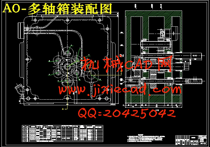
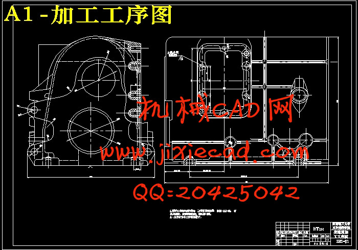
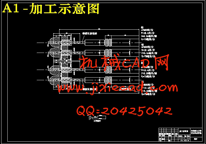
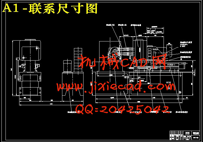
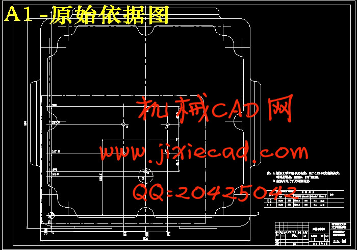
本次的设计题目为汽车变速箱前后面孔系钻削攻丝组合机床设计。汽车变速箱零件上的孔数多,如果采用普通的钻床加工效率低,精度也比较低。特别是对于生产批量大的工件,采用专用的钻孔组合机床能提高生产率和精度。首先是组合机床的总体设计,包括制定工艺方案、确定机床配置形式、制订影响机床总体布局和技术性能的主要部件的结构方案。主要工作是“三图”(加工零件工序图、加工示意图和机床联系尺寸总图)的设计和绘制,这些是组合机床设计的基础。机床联系尺寸图有很多是标准组件,如动力滑台、侧底座等。再来就是技术设计,主要是多轴箱装配图、夹具设计及其装配图。机床多轴箱设计,是本次设计的重点。多轴箱中各个轴的选择和分布是最为关键的也是难点之一,这要根据被加工零件的结构特点及所要加工孔的情况合理地布置各个主轴及传动轴。此外,通过计算各轴工作时所要的功率、扭矩合理地设计各个轴的大小。由于组合机床的自动化程度较高,因而组合机床的夹具和通用机床的夹具是有所不同的,因此采用液压机构进行夹紧,并采用连动销定位。
关键词:组合机床,多轴箱,夹具。
Key Words: modular machine,multiple spindle case,fixture
本次的设计题目为汽车变速箱前后面孔系钻削攻丝组合机床设计。汽车变速箱零件上的孔数多,如果采用普通的钻床加工效率低,精度也比较低。特别是对于生产批量大的工件,采用专用的钻孔组合机床能提高生产率和精度。首先是组合机床的总体设计,包括制定工艺方案、确定机床配置形式、制订影响机床总体布局和技术性能的主要部件的结构方案。主要工作是“三图”(加工零件工序图、加工示意图和机床联系尺寸总图)的设计和绘制,这些是组合机床设计的基础。机床联系尺寸图有很多是标准组件,如动力滑台、侧底座等。再来就是技术设计,主要是多轴箱装配图、夹具设计及其装配图。机床多轴箱设计,是本次设计的重点。多轴箱中各个轴的选择和分布是最为关键的也是难点之一,这要根据被加工零件的结构特点及所要加工孔的情况合理地布置各个主轴及传动轴。此外,通过计算各轴工作时所要的功率、扭矩合理地设计各个轴的大小。由于组合机床的自动化程度较高,因而组合机床的夹具和通用机床的夹具是有所不同的,因此采用液压机构进行夹紧,并采用连动销定位。
关键词:组合机床,多轴箱,夹具。
Abstract
The design topic is design the moduler machine to drill the hole of the speed controller box of The automobiles s in back of department .Because the automobile become soon box has so much holes , if the common drill machines are adopted to drill the holes ,the efficiency will be low and the accuracy is also lower.Especially for produce the quantity of work piece, adopted the combine machine for drill can raise the rate of production and accuracies appropriatively. It is the overall designing which makes up the lathe at first, What this part will be done is how to design and draw the " three pictures "( processing part process picture, process sketch map, lathe get in touch with size general drawing ), these make up the foundation of designing of the lathe . The lathe get in touch with size general drawing has a lot of standard module, such as power slippery platform, incline base part etc .Socend It is the technique designing, mainly the lathe many axle case designing and the lathe’s tongs design and it’s assembles the diagram. the focal point of the many axle case designing, and it each choice and distribution of axle is the most key, so calculate every axle power, torsion wanted design each size of axle rational when working. Through analyse and process the situation of the hole, design the distribution of the main shaft..Because the automation degree of the moduler machine is higher, making up lathe’s tongs and ordinary tongs of lathe are different, adopt hydraulic pressure organization clamp, and adopt and move and sell and make a reservation in succession.Key Words: modular machine,multiple spindle case,fixture
目录
摘要Abstract 2
目录 3
1 绪 论 1
2 组合机床的组成、特点和设计步骤 3
2.1组合机床的组成及特点 3
2.2组合机床的设计步骤 4
3 制定机械加工工艺过程 6
3.1工艺方案的拟订 6
3.2被加工零件的工艺分析及其工艺方案 7
3.2.1 被加工零件的结构特点 7
3.2.2 被加工零件的技术要求和加工工序 8
3.2.3零件的生产批量 9
3.3 制定工艺方案时应考虑问题 9
3.3.1定位基准的及夹压点选择 9
3.3.2加工工艺方案 10
4 加工工序图 12
4.1被加工零件工序图 12
4.1.1被加工零件工序图的作用及内容 12
5 加工示意图 14
5.1切削用量的选择 14
5.1.1 确定切削用量应注意的问题 14
5.1.2组合机床切削用量的选择 15
5.2 选择刀具结构 17
5.3加工示意图 18
5.3.1加工示意图的作用和内容 18
5.3.2.加工示意图的画法及注意事项 18
5.3.3.择刀具、工具、导向装置并标注其相关位置尺寸 19
5.3.4初定主轴类型、尺寸、外伸长度和选择接杆 21
5.4动力部件的工作循环和工作行程 22
6 绘制机床联系尺寸总图 24
6.1联系尺寸图的作用及内容 24
6.2 通用部件的选择 24
6.3绘制机床联系尺寸总图之前确定的主要内容 25
6.3.1各主轴切削力P,扭矩M,切削功率N的计算 25
6.3.2动力部件的选择 26
6.3.3机床装料高度的确定 27
6.3.4夹具轮廓尺寸的确定 28
6.3.5中间底座尺寸的确定 28
6.3.6主轴箱轮廓尺寸的确定 29
6.4机床分组 30
7 组合机床主轴箱设计 31
7.1主轴箱的基本结构 31
7.1.1 通用主轴箱的组成 31
7.1.2主轴箱通用零件 31
7.2绘制多轴箱设计原始依据图 32
7.3 主轴、齿轮的确定及动力计算 33
7.3.1主轴型式和直径、齿轮模数的确定 33
7.3.2动力计算 34
7.4主轴箱传动设计 34
7.4.1主轴的分布 35
7.4.2传动系统设计 35
7.5多轴箱坐标计算 37
7.5.1坐标计算 37
7.5.2绘制坐标检查图 38
7.6 主轴箱总图设计 38
7.7 攻丝主轴箱设计 40
8 组合机床夹具设计 41
8.1组合机床夹具概述 41
8.1.1 组合机床的夹具设计特点 41
8.1.2组合机床的夹具的设计过程 42
8.2 定位支承系统 42
8.2.1定位方案 42
8.2.2定位销的液压控制 43
8.2.3 定位误差计算 44
8.3 导向装置 46
8.4夹紧机构 46
8.4.1 夹紧方案 46
8.4.2夹紧力的计算 46
毕业设计总结 49
参考文献 51
致 谢 52


