设计简介
摘 要
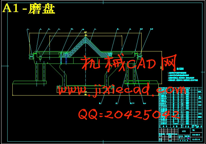
辊磨机(又称立磨)是一种用途很广的粉磨兼烘干设备,立式辊磨是目前世界上比较先进而且成型的技术,它不但具有能耗低、产量高、维修工作量小等优点,而且运转周期长,适合与大型窑外分解窑配套。在用立磨粉磨物料时,磨辊和磨盘的磨损比较大、国外一些立磨生产厂在磨辊和磨盘等易碎件上使用了更耐磨的材料。因此,其生产的立磨成功地用于水泥和矿渣粉磨中。本文总结了这些立磨的易损件材料选择的一些成功经验,并将其性能及其磨损情况进行对比分析。
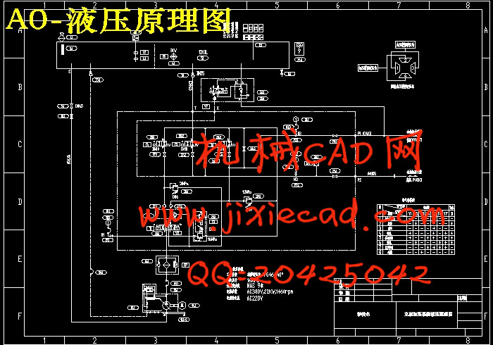
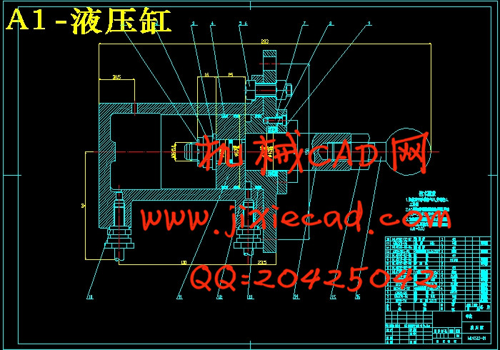
现代的立磨随着液压技术的发展普遍采用液力加压系统向磨辊加力,压力加载是通过油缸实现的,调控液压系统的压力可改变油缸对磨辊压力的情况,可随意调控磨辊对物料粉磨力的大小。液压系统内的储能器对磨辊设施具有保压和过载缓冲的作用,可吸收一部分过载压力。
关键词:立磨;磨损;液压;储能器
Abstract
The roller gringing machine (has name to stand rubs )is one kind of use very broad powder rubs concurrently dries the equipment .The vertical roller rubs is in the present world quite, advanced the technology which moreover takes shape ,it not only has the energy consumption lowly .the output high ,the service work load young and soon the characteristic ,moreover the operating cycle is long ,suit decomposes the kiln with the large –scale kiln outside to from acompleteset . To reduce the abrasion of rollers and millstones of the roller mill , the high quality materials have to be used , and then the roller mills arc able to be used to produce cement and GGBS successfully in abroad . In this paper , the successful experience to select the materials for the parts of the mill was sunnrized with the comparison of materials properties and rate of abrasion .
The modern age stands rubs uses the fluid strength compression system along with the hydraulic technique development to the roll thrust augmentation .the pressure load is generally realizes through the cylinder ,the regulation hydraulic system’s pressure may change the cylinder to the roll thrust augmentation condition ,may regulate the roll to rub the strength at will to the material powder the size . In hydraulic system’s accumulator has to the roll facility guarantees pressers and overloads the cushioning effect ,may absorb a part of overload pressure .
Ker words : roller mill;abrasion;hydraulic pressure;accumulator
目 录
第一章 前言 2
第二章 总体方案 4
2.1.设计方案 4
第三章 加压装置结构设计 6
3.1 磨辊宽度的确定 6
3.2 磨盘转速的确定 6
3.3磨辊的压力的确定 7
3.4所需功率的确定 8
3.5液压缸的确定 8
第四章 液压原理图的确定 10
4.1.实现功能 10
4.2 拟定液压原理图 11
第五章 液压元件的选型与计算 12
5.1 液压系统主要参数计算 12
5.1.1 选系统工作压力 12
5.1.2 液压缸主要参数的确定 12
5.1.3 液压缸强度校核 13
5.1.4 液压缸稳定性校核 15
5.1.5 计算液压缸实际所需流量 17
5.2 液压阀的选择 18
5.2.1 液压阀的作用 18
5.2.2 液压阀的基本要求 18
5.2.3 液压阀的选择 18
5.3 液压泵站 19
5.3.1 液压泵站概述及液压泵站油箱容量系列标准 19
5.3.2 各系列液压泵站的简述 20
5.4 液压泵 21
5.4.1 液压泵的选择 21
5.4.2 液压泵装置 22
5.5 电动机功率的确定 23
5.6 液压管件的确定 24
5.6.1 油管内径确定 24
5.6.2 管接头 24
5.7 滤油器的选择 25
5.7.1 滤油器的作用及过滤精度 25
5.7.2 选用和安装 25
5.8 油箱及其辅件的确定 26
5.8.1 油箱 26
5.8.2 空气滤清器 28
5.8.3 油标 28
第六章 液压缸的设计计算 29
6.1 液压缸的基本参数的确定 29
6.2 液压缸主要零件的结构、材料及技术要求 30
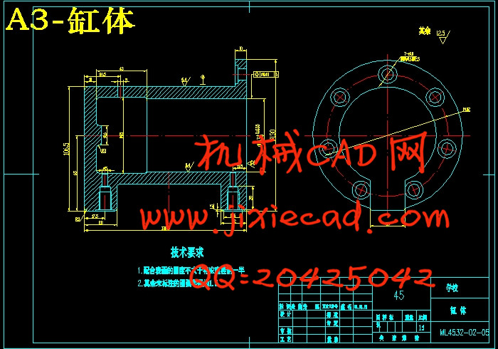
6.2.1 缸体 30
6.3 缸盖 32
6.3.1 缸盖的材料 32
6.4 活塞 33
6.4.1 活塞与活塞杆的联接型式 33
6.4.2 活塞与缸体的密封 33
6.4.3 活塞的材料 34
6.4.4 活塞的技术要求 34
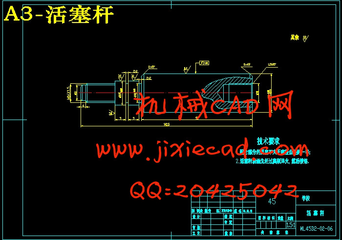
6.5 活塞杆 34
6.5.1 端部结构 34
6.5.2 端部尺寸 35
6.5.3 活塞杆结构 36
6.5.4 活塞杆材料 36
6.5.5 活塞杆的技术要求 36
6.6 活塞杆的导向、密封和防尘 37
6.6.1 导向套 37
6.6.2 杆的密封与防尘 37
6.7 液压缸的缓冲装置 37
结论 39
致 谢 40
参考文献 41


