设计简介
摘 要
加工中心由于备有刀库并能自动更换刀具,使得工件在一次装夹中可以完成多工序的加工。加工中心一般不需要人为干预,当机床开始执行程序后,它将一直运行到程序结束。加工中心还赋予了专业化车间一些诸多优点,如:降低机床的故障率,提高生产效率,提高加工精度,削减废料量,缩短检验时间,降低刀具成本,改善库存量等。由于加工中心的众多优势,所以它深受全球制造企业的青睐。
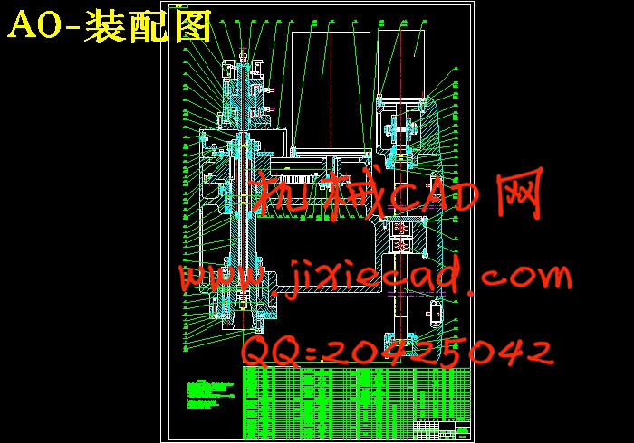
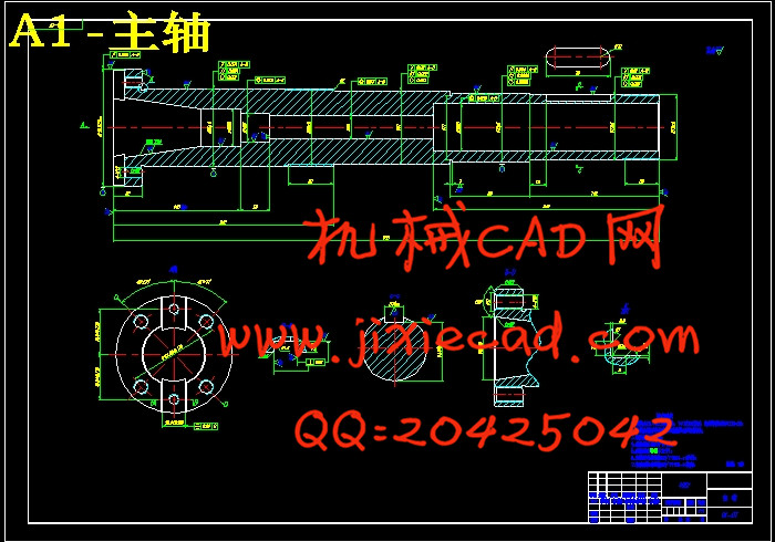
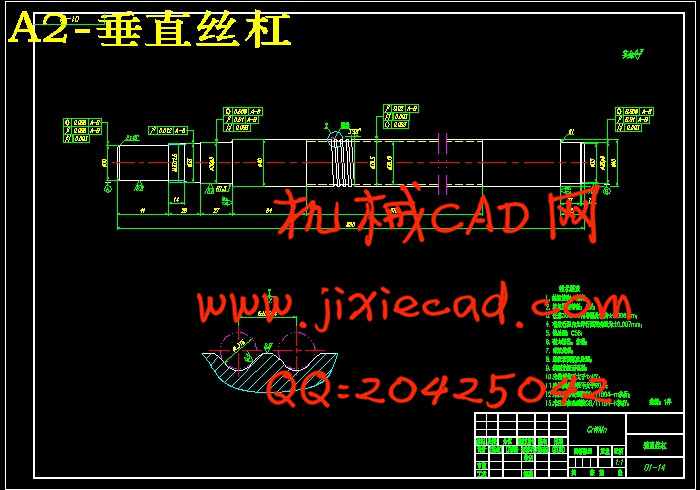
加工中心主要由主轴组件、回转工作台、移动工作台、刀库及自动换刀装置以及其它机械功能部件组成。其中的主轴组件是机床重要的组成部分,其运动性能直接影响机床加工精度与表面粗糙度。本文在查阅大量国内外文献的基础上,通过研究分析不同加工中心主轴组件的性能,综合地比较了其特点,并拟定了一个较为合理的主轴组件结构方案。同时,还就主轴、轴承以及丝杠等重要零件的机械性能进行了探讨,并对这些零件的刚度和强度进行了校核。此外,本设计中所采用的陶瓷轴承能有效地增加主轴的刚度,从而提高了加工中心的可靠性和稳定性。
关键词:主轴组件,加工中心,数控机床
Spindle unit design of Vertical machining center
ABSTRACT
Machining center evolved from the need to be able to perform a variety of operations and machining sequences on a workpiece on a single machine in one setup. Machining center requires little operator intervention, and once the machine has been set up, it will machine without stopping until the end of the program is reached. Some of the other advantages that machining centers give a manufacturing shop are greater machine uptime, increased productivity, maximum part accuracy, reduced scrap, less inspection time, lower tooling costs, less inventory and so on. Because of their many advantages, machining centers become widely accepted by manufacturing enterprises in the world.
Machining centers are equipped with spindle units, rotary workbench, moving workbench, tool magazines and automatic tool changers, and other mechanical function components. Spindle unit is the important motion part of the metal cutting machine tool. Its movement behavior affects the machining accuracy and surface roughness of part to be machined. Through referring to a variety of technical literatures, the characteristics of some kinds of spindle units are compared with each other based on analysis and research work on different machining centers. A reasonable scheme can be studied out. Meanwhile, the mechanical behaviors of principle parts such as the spindle, bearings and lead screw are discussed. Their rigidity and strength are calculated and examined here. Morever, a kind of advanced ceramic bearings is introduced into the spindle unit, which can effectively enhance the rigidity of spindle units. They will improve the reliability and stability of machining centers.
Key words:spindle unit,machining center,NC machine tool
目 录
摘要…………………………………………………………………… 1
ABSTRACT……………………………………………………………… 2
0 引言………………………………………………………………… 4
1 概述………………………………………………………………… 5
1.1 加工中心的发展状况…………………………………………… 5
1.1.1 加工中心的国内外发展……………………………………… 5
1.1.2 主轴部件的研究进展………………………………………… 6
1.2 课题的目的及内容……………………………………………… 7
1.3 课题拟解决的关键问题………………………………………… 8
1.4 解决上述问题的策略…………………………………………… 9
2 方案拟定…………………………………………………………… 10
2.1 加工中心主轴组件的组成……………………………………… 10
2.2 机械系统方案的确定…………………………………………… 10
2.2.1 主轴传动机构………………………………………………… 10
2.2.2 主轴进给机构………………………………………………… 12
2.2.3 主轴准停机构………………………………………………… 13
2.2.4 刀具自动夹紧机构…………………………………………… 15
2.2.5 切屑清除机构………………………………………………… 17
2.3 伺服驱动系统方案的确定……………………………………… 18
2.4 加工中心主轴组件总体设计方案的确定……………………… 19
3 主轴组件的主运动部件…………………………………………… 22
3.1 主轴电动机的选用……………………………………………… 22
3.1.1 主电机功率估算……………………………………………… 22
3.1.2 主电机选型…………………………………………………… 23
3.2 主轴……………………………………………………………… 23
3.2.1 主轴的结构设计……………………………………………… 23
3.2.2 主轴受力分析………………………………………………… 27
3.2.3 主轴的强度校核……………………………………………… 32
3.2.4 主轴的刚度校核……………………………………………… 33
3.3 主轴组件的支承………………………………………………… 34
3.3.1 主轴轴承的类型……………………………………………… 34
3.3.2 主轴轴承的配置……………………………………………… 37
3.3.3 主轴轴承的预紧……………………………………………… 38
3.3.4 主轴支承方案的确定………………………………………… 41
3.3.5 轴承的配合…………………………………………………… 41
3.3.6 主轴轴承设计计算…………………………………………… 42
3.4 同步带的设计计算……………………………………………… 44
3.5 主轴组件的润滑与密封………………………………………… 48
3.5.1 主轴组件的润滑……………………………………………… 48
3.5.2 主轴组件的密封……………………………………………… 49
3.5.3 本课题的润滑与密封方案的确定…………………………… 51
3.6 键的设计计算…………………………………………………… 52
3.6.1 主轴上的键…………………………………………………… 52
3.6.2 主电机上的键………………………………………………… 53
3.7 液压缸的设计计算……………………………………………… 54
4 主轴组件的进给运动部件………………………………………… 55
4.1 进给电动机的选用……………………………………………… 55
4.1.1 进给电动机功率的估算……………………………………… 55
4.1.2 进给电动机的选用…………………………………………… 56
4.2 联轴器的设计计算……………………………………………… 57
4.3 垂直方向伺服进给系统的设计计算…………………………… 57
4.3.1 切削力估算…………………………………………………… 57
4.3.2 滚珠丝杠副的设计计算……………………………………… 58
5 结论………………………………………………………………… 65
小结…………………………………………………………………… 68
参考文献……………………………………………………………… 70


