设计简介
摘要
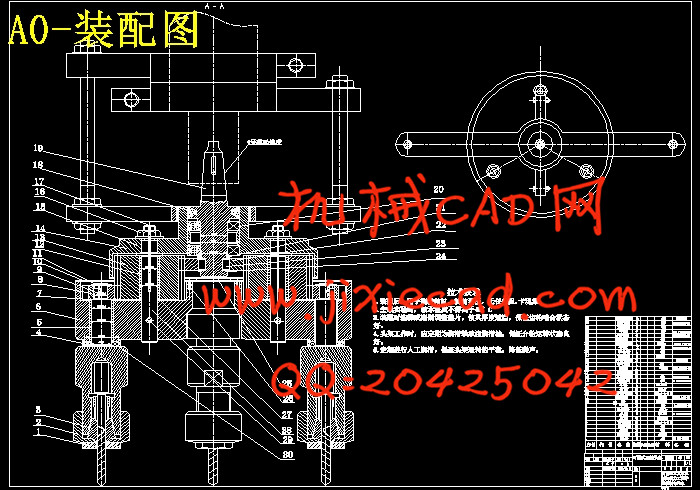
本文是立式钻床用轴均布多轴头设计,可调式多轴头各轴在圆周方向均布且方向可方便地沿直径方向同步调整,以适应多种小批量生产条件下法兰盘类零件的螺孔加工。固定试式多轴头是根据一个典型法兰盘类零件而设计的,用于零件中大批量生产要求。
多轴头架的设计参数来源于一般的加工工艺条件,以适应更广阔的加工范围。针对工厂里多孔钻削时,孔径一般较小,多在10cm左右,而且大部分是箱体、法兰盘等,箱体、法兰盘多为铸造件,材料是铸铁,也有个别的被加工零件的材料是低碳钢。根据这些工件的切削条件,可以确定多轴头架的工艺主参数。
主参数确定后便可以进行多轴头架的总体设计。多轴头架的传动原理是通过齿轮啮合增加钻削轴的轴数,以满足多孔加工的要求。通过二级齿轮啮合,输入轴和输出轴的转向没变,但由于齿轮分支传动,变成多根输出轴。
为了保证加工生产条件的安全,加上多轴头工作时装隔离装置比较困难,所以必须严格校核轴头架的强度,以免发生事故或达不到加工要求。
可以看出,改装后的多轴钻床,可以同时完成多个孔的钻、扩、铰等工序。工艺范围可以满足一般加工情况的孔类钻削要求。可调多轴头架可以起到提高生产效率、降低成本、提高孔系加工精度等作用。参照该调节原理可进行其他任意孔系加工装置的设计,还可以用于攻丝、扩、锪孔等加工装置。此外该装置具有结构简单、操作方便、应用范围广等特点,值得推广。
关键词:立式 钻床 多轴头 可调 固定
Abstract
The design of multiple spindles heads for drilling machine whose drills spindles are adjustable or fixed are introduced
The adjustable spindles of the multiple spindles heads are located evenly in the circuit and can be adjusted synchronism on the diameter’s direction to meet the small scale production needs of the screw hole manufacture for flange plate parts.And the fixed multiple spindles heads is design for the big scale production needs of the screw hole manufacture for flange plate parts,it can’t be used to manufacture another farts, because it’s spindle distance is designed for the only part.
The design of multiple spindles heads include three parts : the total design, the transfer system design , and the constructive design
Because of the un-development in our manufacture industry ,most company’s plant lack of the machine to drill multiple holes at the same time , and it’s a waste of funding on the manufacturing facilities which will be laid after the parts are produced . so the economic multiple spindles heads enable the normal company to drill the multiple holes in a fast way .And same company gained the economic performance by the way of reequips the machine tools. It’s the fact that the reequipped drilling machine can satisfy the process precision requirement .so the design is feasible.
Based on the design of the multiple spindles heads , we can also design the others to the manufacture of the other flange plant parts.
Key words: drilling machine ;adjustable; multiple spindles heads;
目录
前言………………………………………………………………………………1
1. 概述……………………………………………………………………..2
1.1 问题的提出……………………………………………………….2
1.2 同行业概况……………………………………………………….2
1.3 课题的意义……………………………………………………….2
2. 总体方案设计…………………………………………………………4
2.1 对工件进行工艺分析……………………………………………4
2.1.1 检查图纸的完整性和正确性…………………………...4
2.1.2 分析工件的结构特点…………………………………...4
2.1.3 分析工件的材料及加工性能…………………………...5
2.1.4 工件的生产批量………………………………………...5
2.2 确定工件的加工方法……………………………………………5
2.3 对被改装钻床的分析……………………………………………5
2.4 总体布局…………………………………………………………6
2.5 其他问题分析……………………………………………………7
3. 齿轮可调式三轴头架的设计…………………………………………8
3.1 齿轮可调式三轴头架的传动原理及调整方法…………………8
3.2 方案的工艺设计参数……………………………………………9
3.2.1 Z535钻床动力所允许的工况条件…………………….9
3.2.2 确定用于钻削计算的极限值………………………….13
3.3 三轴头架的传动设计…………………………………………..16
3.3.1 齿轮的设计验算………………………………………16
3.3.2 轴的设计与校核………………………………………21
3.3.3 轴承的校核计算………………………………………35
3.3.4 键的设计校核…………………………………………37
3.3.5 螺栓的设计校核………………………………………38
3.3.6 夹头夹紧力的计算校核………………………………40
4. 润滑与密封…………………………………………………………43
5. 结束语………………………………………………………………44
6. 谢辞…………………………………………………………………46
7. 参考文献…………………………………………………………….47


