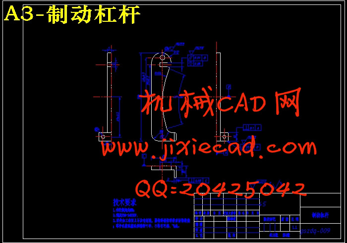
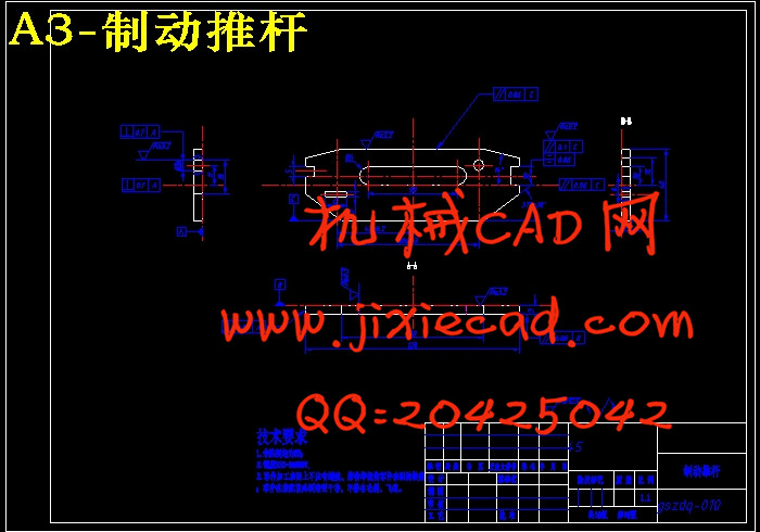
设计简介
摘要
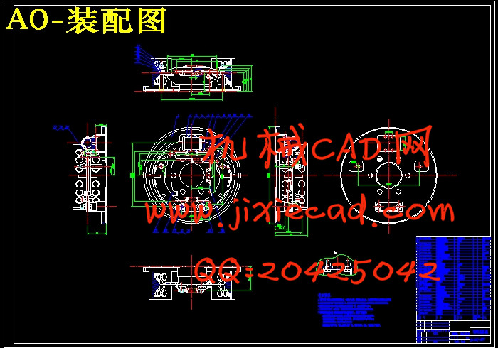
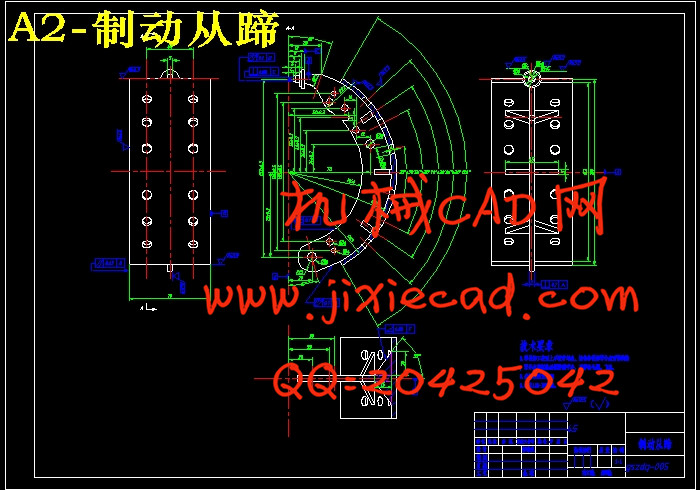
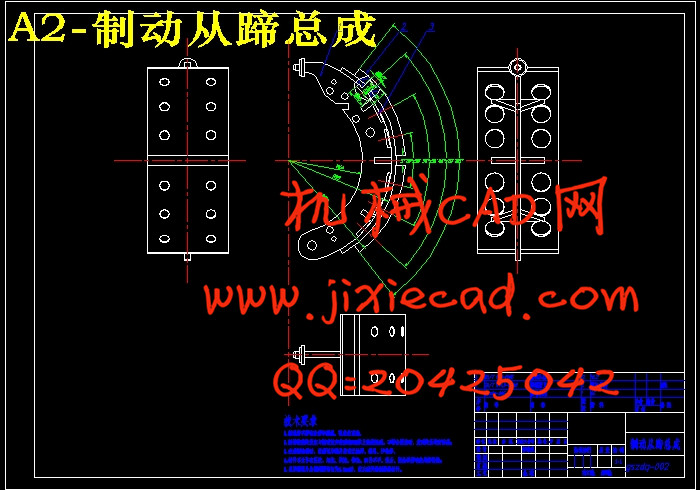
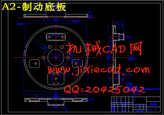
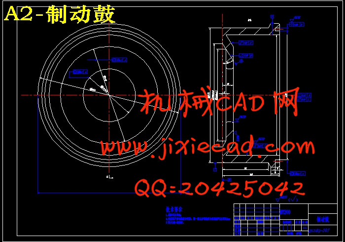
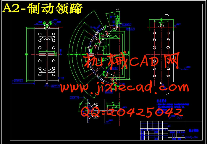
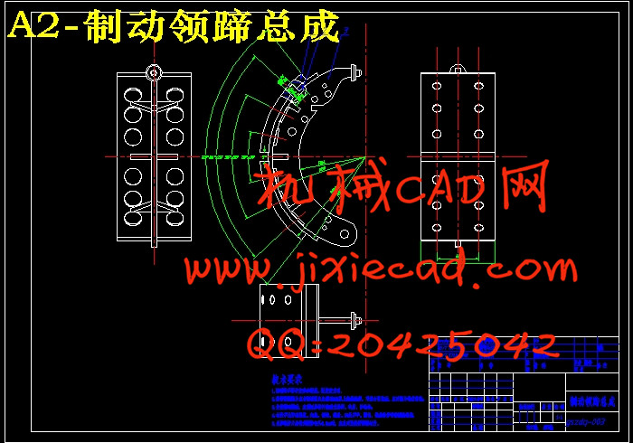
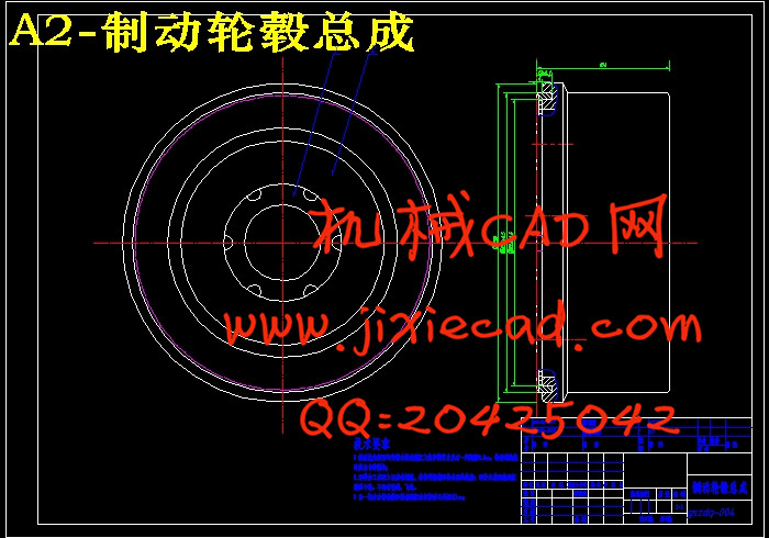
设计一款制动效能高、工作稳定性好的制动器对汽车的汽车在行驶过程中的安全性和可靠性具有重要意义。本文根据桑塔纳2000的性能参数,设计与开发了一种能够满足使用要求的领从蹄式鼓式制动器。主要内容包括领从蹄式鼓式制动器的总体方案设计、制动器的主要参数的确定、制动器促动系统的设计、领从蹄式鼓式制动器的主要零部件的结构强度校核、领从蹄式鼓式制动器三维模型的建立,领从蹄式鼓式制动器装配图和零件图的绘制;总体方案设计内容包括分析比较不同类型的鼓式制动器特点,结合桑塔纳2000的性能要求,确定了采用领从蹄式鼓式制动器作为桑塔纳2000后轮制动器的总体方案;制动器的主要参数包括制动力和制动力分配系数、同步附着系数、制动强度和附着系数利用率、制动器最大制动力矩、制动器的结构参数与摩擦系数;促动系统的设计包括促动装置选型、制动管路的回路选型、制动轮缸直径和工作容积制动踏板力和制动行程、制动力矩、制动器热容量等结构参数;分析了制动蹄压力分布规律和径向变形规律、行车制动效能、摩擦衬片的磨损特性、温升的核算、驻车制动极限倾角等性能参数;完成了制动臂、制动凸轮轴、制动蹄支承销、紧固摩擦片铆钉等主要零部件的结构强度校核;通过结构设计、结构强度校核、三维模型建立及工程图的绘制,最终完成了领从蹄式鼓式制动器的设计。
关键词:鼓式制动器;促动系统;制动力矩;三维模型
ABSTRACT
Design a high efficiency and good stability brake for auto car is of great significance in the process of driving safety and reliability. A leading trailing shoe drum drakes that can meet the use requirements for santana 2000 is designed and developed based on the performance parameters of Santana 2000. it mainly includes the overall scheme design of leading trailing shoe drum drakes、Determine the main parameters of the brake、The design of brake actuation system、The structural strength check of leading trailing shoe drum drakes major parts、The establishment three-dimensional model of leading trailing shoe drum drakes、The assembly drawing and part drawing of leading trailing shoe drum drakes; The overall scheme contains Analysis of drum brake characteristics comparison of different types, combined with the performance requirements of Santana 2000, the leading and trailing shoe brake as the overall design of the design object; the main parameters include brake braking force and braking force distribution coefficient, the synchronous adhesion coefficient, brake strength and attachment structure parameters and coefficient of friction coefficient, utilization rate the maximum brake braking torque, brake design; actuation system including actuating device selection, calculation of loop wheel brake cylinder diameter and the volume of work of brake pedal and the braking distance, braking torque, brake thermal capacity and structure parameters such as brake pipeline, analysis of brake shoe pressure distribution and radial deformation, braking efficiency, friction lining wear characteristics, Wen Sheng's accounting, Parking brake limit angle; Completed the structural strength checking brake arm, brake camshaft, brake shoe anchor pin, fastening lining rivets and other major components; Form the structural design, structural strength check, three-dimensional modeling and rendering drawings, the assigned designing of leading trailing shoe drum drakes is completed.
Keywords: drum brakes;Actuation system;brake torque;three-dimensional model
目录
第一章 绪论…………………………………………………………………………… 1
1.1 本课题的研究意义……………………………………………………………… 1
1.2 鼓式制动器技术研究进展和现状……………………………………………… 1
1.3 研究内容………………………………………………………………………… 3
第二章 鼓式制动器的结构方案设计…………………………………………… 4
2.1 鼓式制动器的结构型式与分类………………………………………………… 4
2.2 鼓式制动器的设计方案确定…………………………………………………… 8
第三章 制动系的主要参数设计………………………………………………… 11
3.1 预给的整车参数………………………………………………………………… 11
3.2 制动力与制动力分配系数……………………………………………………… 11
3.3 同步附着系数…………………………………………………………………… 14
3.4 制动强度和附着系数利用率…………………………………………………… 15
3.5 制动器最大制动力矩…………………………………………………………… 15
3.6 鼓式制动器的结构参数与摩擦系数 ………………………………………… 16
第四章 制动器的设计计算………………………………………………………… 19
4.1 制动驱动机构的结构型式选择………………………………………………… 19
4.2 制动管路的多回路系统………………………………………………………… 20
4.3 液压制动驱动机构的设计计算………………………………………………… 21
4.3.1 制动轮缸直径与工作容积……………………………………………… 21
4.3.2 制动主缸直径与工作容积……………………………………………… 22
4.3.3 制动踏板力与踏板行程………………………………………………… 22
4.4 制动蹄片上的制动力矩计算…………………………………………………… 23
4.5 制动器因数的分析计算 …………………………………………………… 27
4.6 制动蹄压力分布规律及径向变形规律………………………………………… 29
4.7 行车制动效能计算……………………………………………………………… 31
4.8 摩擦衬片的磨损特性计算……………………………………………………… 32
4.9 制动器热容量和温升的核算…………………………………………………… 34
4.10 驻车制动计算…………………………………………………………………… 35
第五章 制动器主要零部件的结构设计与强度计算………………………… 37
5.1 制动器主要零部件的结构设计………………………………………………… 37
5.1.1 制动鼓…………………………………………………………………… 37
5.1.2 制动蹄…………………………………………………………………… 38
5.1.3 制动底板………………………………………………………………… 38
5.1.4 制动蹄的支承…………………………………………………………… 38
5.1.5 制动轮缸………………………………………………………………… 39
5.1.6 制动摩擦衬片材料……………………………………………………… 39
5.1.7 摩擦材料………………………………………………………………… 39
5.1.8 制动器间隙调整………………………………………………………… 40
5.2 制动器主要零件的强度计算…………………………………………………… 41
5.2.1制动臂的计算…………………………………………………………… 41
5.2.2 制动凸轮轴的计算……………………………………………………… 42
5.2.3 制动蹄支承销剪切应力计算…………………………………………… 42
5.2.4 紧固摩擦片铆钉的剪切应力验算……………………………………… 43
第六章 结论………………………………………………………………………… 45
参考文献………………………………………………………………………………… 46
致谢……………………………………………………………………………………… 47
附录A 主要设计参数………………………………………………………………… 48


