设计简介
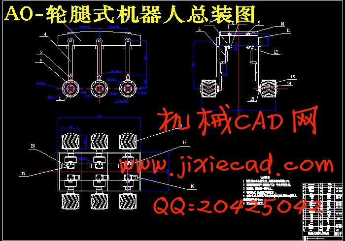
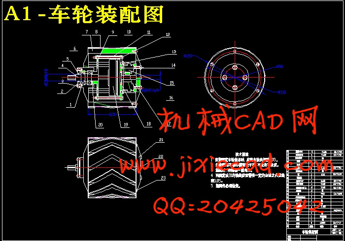
设计了一种能适应不同野外环境的移动机器人,其驱动系统为轮腿式.利用轮腿结合的方式实现越障,具有很强的越障能力.机器人采用六轮腿结构.保障了机器人的平稳性,本文对六轮腿式移动越障机器人驱动装置整体结构作了设计,通过对车轮,腿臂,车身等进行设计,对电机,制动器,减速器等进行选型,对机器人做了性能分析,步态分析.在Pro/E 设计环境下,对整个机器人进行装配,排除干涉.验证结构的正确性.并且在CAD内画出了机构的装配图.
关键词 机器人 越障机构 六轮腿式 驱动装置
Abstract
Design a robot work in different environment,it’movessubsystem is design as a leg-wheel type.It can cross very high obstacle,have very stong hindering ability. The robot adopts six legs mechanism. It has safeguarded the robot stability. In this paper, six legged mobile robot obstacle made the overall structure of the design drive, design on wheels, legs, arms, body, etc. Selecting on the motor, brake, reducer selection, etc. Doing performance analysis, gait analysis Of the robot. In the Pro / E design environment, the entire robot assembly, Exclude interference, verify the correctness of the structure . And draw the body within the CAD assembly drawing.
Keywords robot Obstacle sector six leg-wheel system drive equipment
目 次
1 引言……………………………………………………………………………3
1.1 移动机器人的发展概况 …………………………………………………3
1.2 轮腿式移动机器人的发展趋势 …………………………………………3
1.3 轮腿式移动 机器人关键技术的研究 ……………………………………6
1.4 本次设计目的及意义………………………………………………………6
2 轮腿式移动机器人驱动方案设计 …………………………………………7
2.1 课题要求……………………………………………………………………7
2.2 轮腿式机器人结构方案设计………………………………………………7
2.2.1 轮腿配置方案的选择……………………………………………………8
2.2.2 轮腿式机器人的结构方案………………………………………………8
2.2.3 六轮腿的分布方案………………………………………………………8
2.2.4 越障机构的设计…………………………………………………………9
2.2.5 车轮方案设计……………………………………………………………11
2.2.6 总体方案…………………………………………………………………12
3 轮腿式移动机器人驱动装置结构设计………………………………………14
3.1 车轮设计……………………………………………………………………14
3.1.1 车轮直径设计……………………………………………………………14
3.1.2 轮宽的选择………………………………………………………………14
3.2 腿臂的设计 ………………………………………………………………14
3.3 车底盘设计 ………………………………………………………………15
3.4 机构受力分析与计算 ……………………………………………………16
3.4.1 机构重力估计……………………………………………………………16
3.4.2 受力分析…………………………………………………………………16
3.4.3 前排轮翻越台阶时车身受力分析………………………………………17
3.4.4 车轮驱动功率……………………………………………………………20
3.4.5 关节功率计算……………………………………………………………20
3.4.6 轮子驱动转矩计算………………………………………………………20
3.4.7 在斜坡上所需的制动力…………………………………………………20
3.5 驱动装置的设计……………………………………………………………21
3.5.1 驱动方式概述……………………………………………………………21
3.5.2 车轮电机和制动器选择设计……………………………………………22
3.5.3 腿臂驱动电机和减速器,离合器的选择………………………………23
3.6 总体结构图 ………………………………………………………………24
4 零件设计 ……………………………………………………………………25
4.1 零件设计的主要方面 ……………………………………………………25
4.2 零件具体设计 ……………………………………………………………25
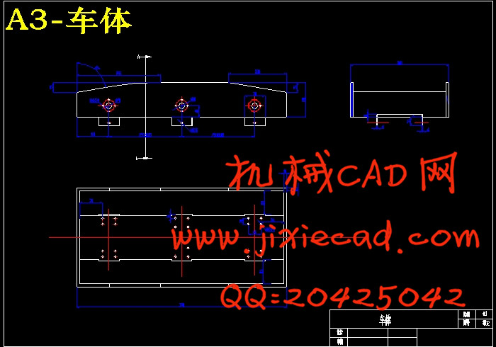
4.2.1 车体的设计 ……………………………………………………………25
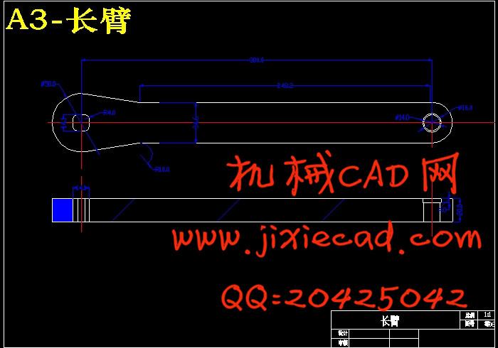
4.2.2 长臂的设计 ……………………………………………………………26
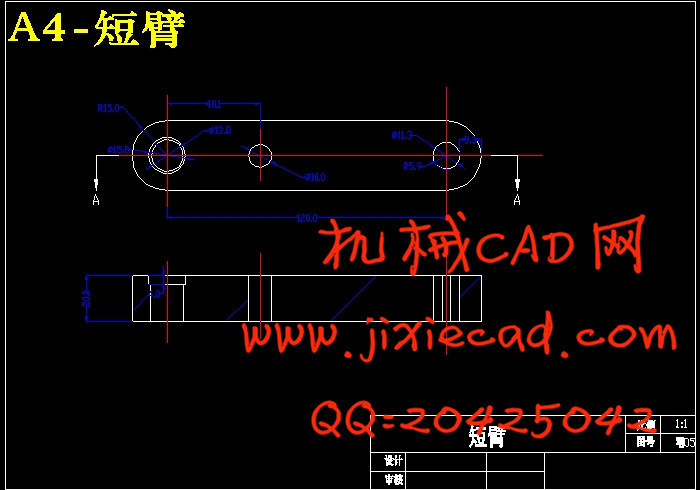
4.2.3 短臂的设计 ……………………………………………………………26
4.2.4 摇杆的设计 ……………………………………………………………26
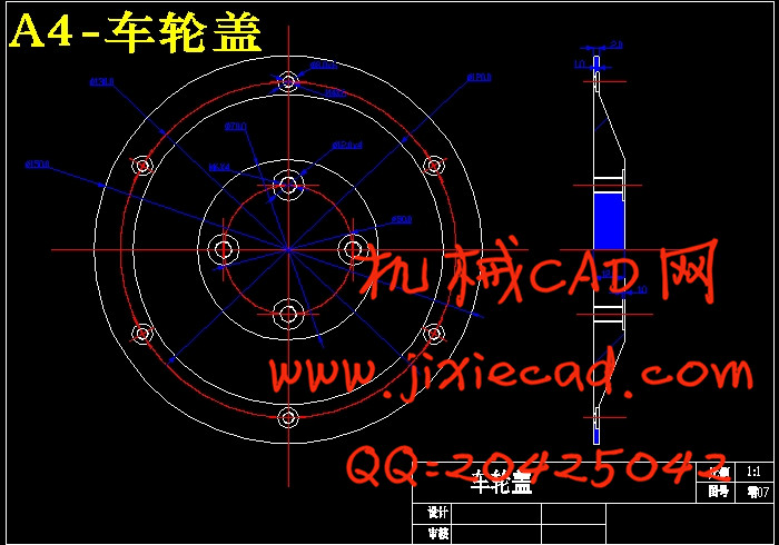
4.2.5 车轮的设计 ……………………………………………………………27
4.2.6 腿臂驱动设计 …………………………………………………………34
4.2.7 整体结构 ………………………………………………………………35
5 性能分析 ……………………………………………………………………36
5.1 动态打滑的稳定性分析 …………………………………………………36
5.2 爬坡步态分析 ……………………………………………………………37
5.2.1 坡面行使 ………………………………………………………………38
5.2.2 越障步态 ………………………………………………………………39
结论………………………………………………………………………………40
致谢………………………………………………………………………………41
参考文献…………………………………………………………………………42


