设计简介
要
液压支架是现代煤矿综采工作面中的配套支护设备,磨擦磨损是其主要结构件。磨擦磨损工作的可靠性直接关系到矿井生产的正常化和工人的生命安全。
随着我国煤炭工业的不断发展,国家对安全生产治理力度的加大,对矿用机电设备的检测技术提出了更高的要求。磨擦磨损性能检测试验台是进行磨擦磨损质量检测的必要设备,是磨擦磨损质量监控的保障。
本文设计的磨擦磨损试验台能够兼容欧洲标准和国家标准,能够检测单根工作阻力达8500kN的磨擦磨损的性能。本文介绍了磨擦磨损性能检测的方法、试验台的组成、原理,设计了加载系统和承载框架。
本设计的主要内容:
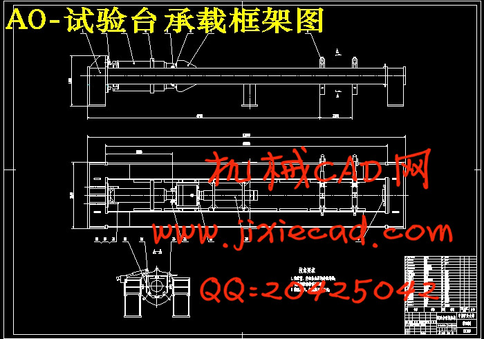
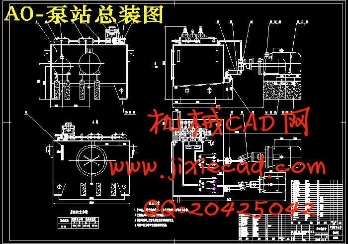
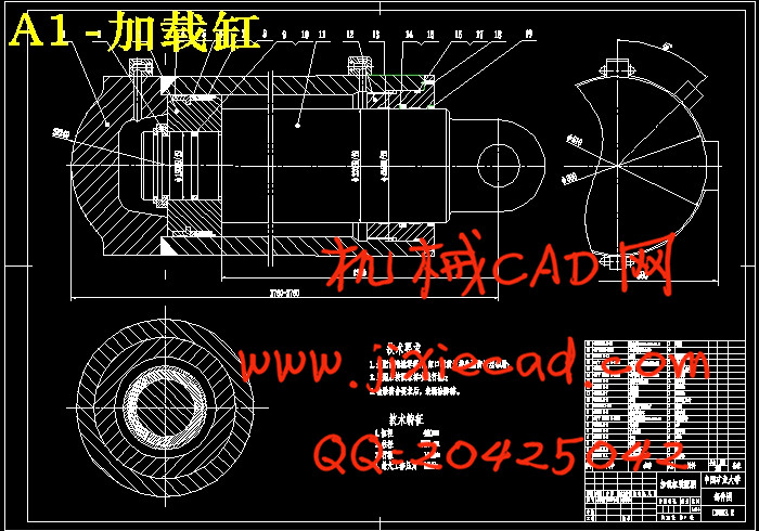
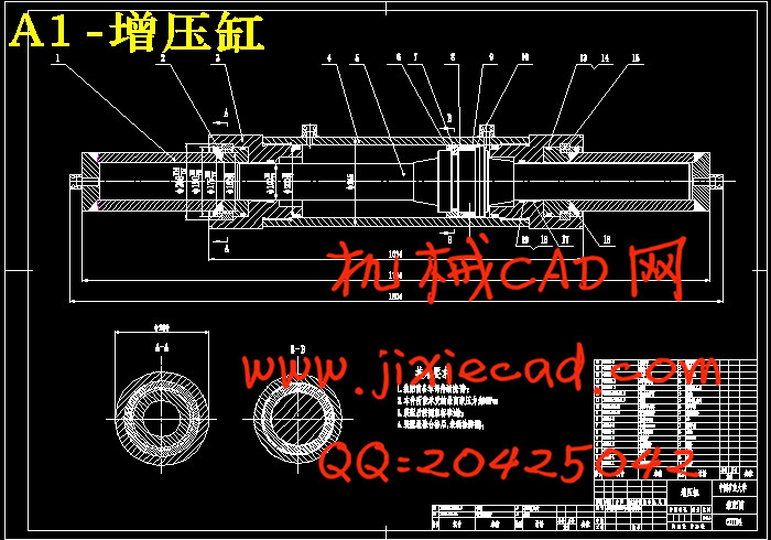
1. 详细设计了外加载系统、加载液压缸、增压缸、油箱、联结罩、联轴器、承载框架。
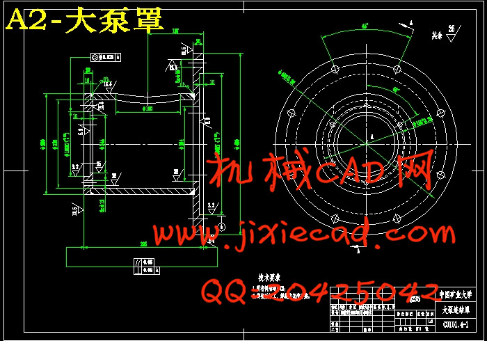
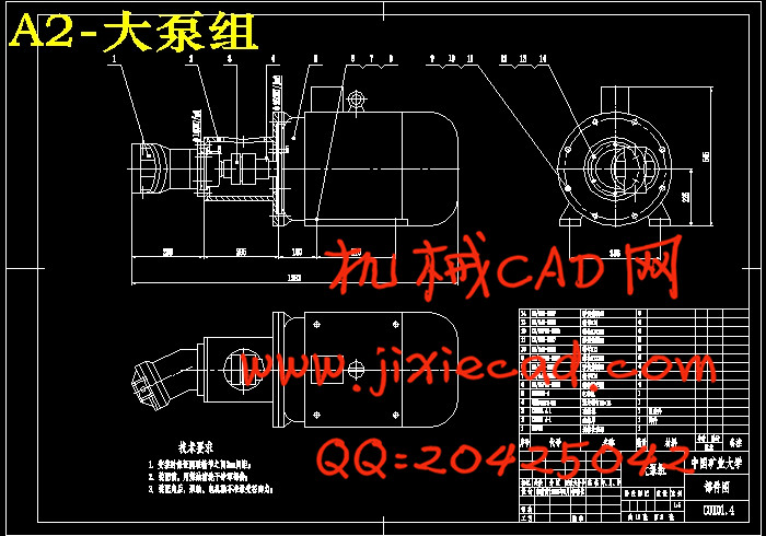
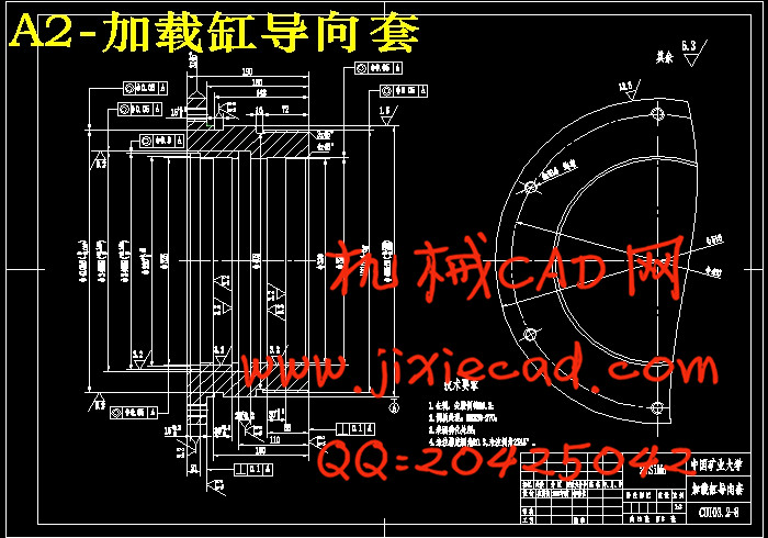
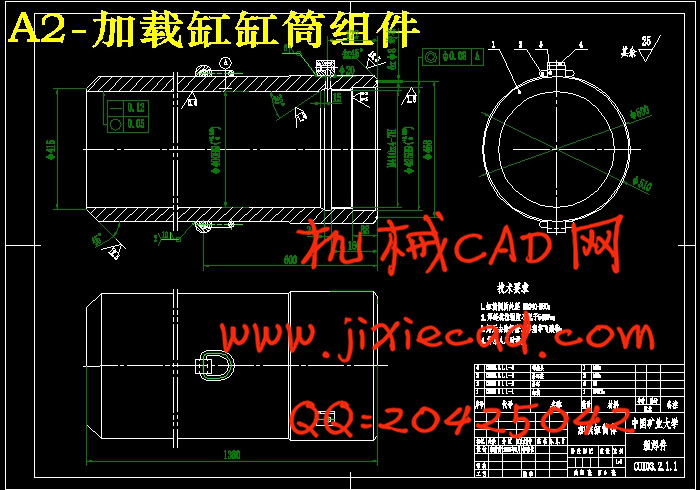
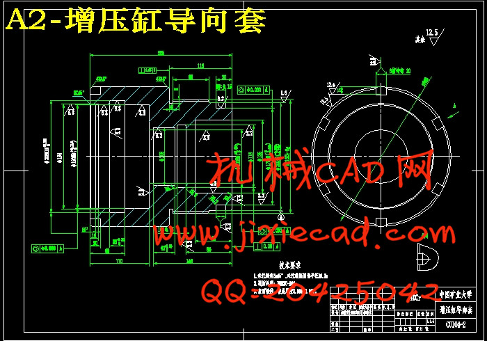
2. 选取外加载泵站、大泵组、增压缸、加载液压缸、联轴器、加载缸导向套等零部件进行了绘图。
3. 承载框架部分,用SolidWorks 2007进行建模,并借助于SolidWorks 2007的一款有限元分析工具COSMOS进行了应力分析。
关键词:液压支架磨擦磨损;液压加载系统;试验台;
ABSTRACT
In the modern mining the hydraulic support is the necessary ancillary equipment, the legs is one of its main elements. The reliability of the legs directly relates the mine pit production normalized and worker's safe.
Along with China coal industry unceasing development, the government to safety dynamics enlarging in production set a higher request to the mineral electromechanical device examination technology.The legs performance test-bed is the legs quality examination of the fittings is the quality monitoring safeguard of the legs.
The legs test-bed of this article designed can compatible European standard and the national standard.,can examine the legs performance of the working resistance reach 8500kN。This article introduced the method of legs performance examination, the test platform composition, designed the loading system and the load bearing frame.
The main content of this article:
1. This article designed the loading system,the hydraulic cylinder,the turbo-charged cylinder, the pumping station fuel tank, joins the cover, the shaft coupling, the load bearing frame in detail.
2. Selected the pumping station of loading, the big pump group, the hydraulic cylinder, the turbo-charged cylinder, the shaft coupling, the cylinder guidance and so on has carried on the cartography.
3. The design of load bearing frame, with the SolidWorks 2007 carries on the design, and drew support to SolidWorks 2007 section finite element analysis tool COSMOS carried on the stress analysis.
Keywords: The Legs of hydraulic support; Hydraulic Loading System; Test-bed;
目 录
1 磨擦磨损试验台总体结构方案设计 1
1.1 课题研究背景和意义 1
1.2 磨擦磨损试验台检测项目和实验方法 1
1.3 拟定试验台总体结构方案 3
2 外加载液压系统设计 5
2.1 液压技术简介 5
2.1.1 液压系统概述 5
2.1.2 液压传动的优点 6
2.1.3 液压技术的缺点 7
2.2 液压加载系统工况分析及设计要求 7
2.3 液压加载系统方案设计 8
2.3.1 选择液压动力源 8
2.3.2 选择执行元件 8
2.3.3 确定控制方式 8
2.3.4 液压回路设计 9
2.3.5 选定液压油类型 11
2.3.6 系统压力、流量的调定和测量 12
2.4 拟定外加载系统原理图 12
2.5 加载液压缸主要参数计算 14
2.5.1 初选液压缸工作压力 14
2.5.2 确定液压缸的主要结构尺寸 14
2.5.3 验算最小稳定速度 15
2.5.4 活塞杆稳定性验算 16
2.6 计算系统压力 17
2.6.1 计算加载缸各工况压力 18
2.6.2 确定系统供油压力 18
2.7 计算系统各工况的流量 18
2.8 液压泵的参数计算与型号选择 19
2.8.1 计算液压泵的最大工作压力 19
2.8.2 确定液压泵的输出流量 20
2.8.3 选择液压泵 21
2.9 与液压泵匹配的原动机的选择 24
2.9.1 计算液压泵各工况的输出功率 24
2.9.2 选择电动机型号 25
2.10 液压元件的选择 26
2.10.1 液压阀类元件的选择 26
2.10.2 过滤器的选择 27
2.10.3 蓄能器的选择 28
2.10.4 液压油管的选择 30
2.10.5 液压油箱容积的计算 34
2.11 外加载液压系统的验算 34
2.11.1 系统的压力损失验算 35
2.11.2 系统的发热温升验算 37
2.12 油箱的设计 38
2.12.1 油箱设计要点 39
2.12.2 确定油箱的外形尺寸 40
2.12.3 油箱的结构设计 42
2.13 泵站结构布置设计 42
2.13.1 液压泵站结构设计的注意事项 42
2.13.2 选择液压泵站安装方式 43
2.13.3 电动机与液压泵的联接方式 43
2.13.4 液压泵站布置方案 44
3 外加载液压缸设计 45
3.1 液压缸的类型及其特点 45
3.2 液压缸主要结构尺寸和性能参数 46
3.3 液压缸缸筒和缸盖的计算 46
3.3.1 缸筒和缸盖的结构形式 46
3.3.2 确定缸筒的壁厚 48
3.3.3 确定液压缸的外径 48
3.3.4 缸筒壁厚的验算 48
3.3.5 缸盖厚度的计算 50
3.4 缸体长度的确定 51
3.5 活塞的最小导向长度H的确定 52
3.6 导向套尺寸配置 52
3.6.1 导向套受力分析 52
3.6.2 导向套尺寸与加工要求 54
3.7 液压缸油口直径的计算 55
3.8 活塞杆组件的尺寸计算 56
3.8.1 活塞杆组件的组成与材料 56
3.8.2 活塞尺寸计算及连接方式选择 56
3.9 加载缸密封圈的选择 59
3.9.1 密封装置类型选择 59
3.9.2 密封圈材料的选择 64
3.10 液压缸设计注意的问题 64
4 增压液压缸设计 66
4.1 增压液压缸工作原理 66
4.1.1 增压回路 66
4.1.2 增压液压缸结构 67
4.2 增压缸主要结构尺寸计算和性能参数确定 68
4.2.1 已知增压缸参数 68
4.2.2 确定增压缸的主要结构尺寸 68
4.2.3 确定液压缸的増压行程 69
4.3 增压缸大缸筒的计算 70
4.3.1 大缸筒和两缸盖的结构形式 70
4.3.2 确定大缸筒的壁厚 70
4.3.3 确定增压缸大缸筒的外径 71
4.3.4 大缸筒壁厚的验算 71
4.4 增压缸小缸筒的计算 73
4.4.1 小缸筒和两缸盖的结构形式 73
4.4.2 确定小缸筒的壁厚 74
4.4.3 确定小钢筒的外径 75
4.4.4 小缸筒壁厚的验算 75
4.5 缸体长度的确定 76
4.6 活塞的最小导向长度H的确定 77
5 试验台承载框架结构设计 78
5.1机架设计的准则和要求 78
5.1.1 机架设计的准则 78
5.1.2 机架设计的一般要求 78
5.1.3 机架设计的传统步骤 79
5.2 承载框架的结构选型与三维建模 79
5.2.1 选择机架形式与钢板材料 79
5.2.2 三维设计应用的趋势 80
5.2.3 选择三维设计软件的关键考虑因素 81
5.2.4 SolidWorks的功能 81
5.3 承载框架的有限元分析 82
6 结 论 89
参考文献 90
附 录 92
附录Ⅰ 内加载系统原理图与选型 92
附录Ⅱ 框架单侧承载梁应力分布图 94
附录Ⅲ 框架单侧承载梁位移分布图 95
附录Ⅳ SolidWorks最新版本SolidWorks® 2007概述 96
附录Ⅴ COSMOS 2007简介 99
致 谢 102


