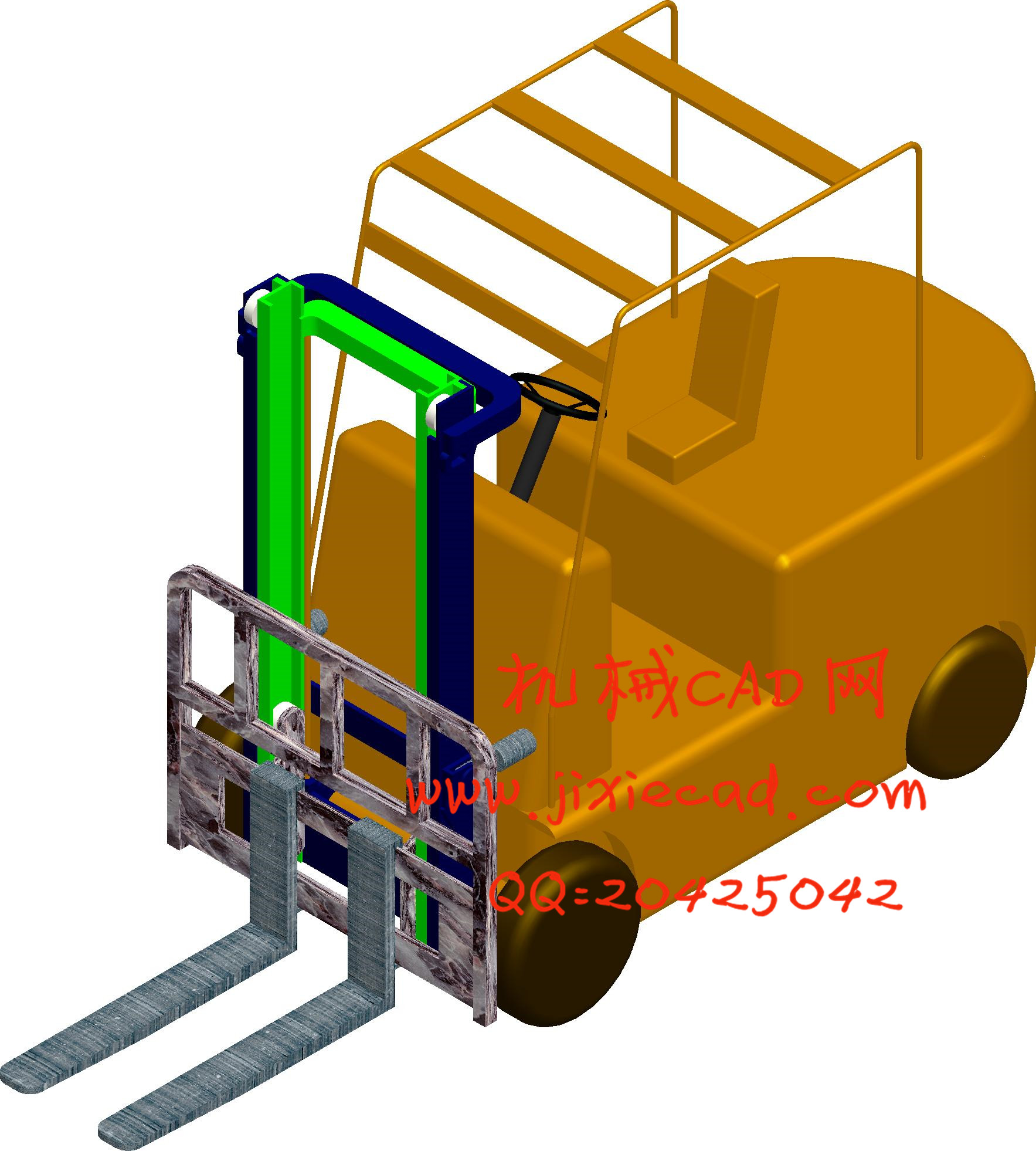
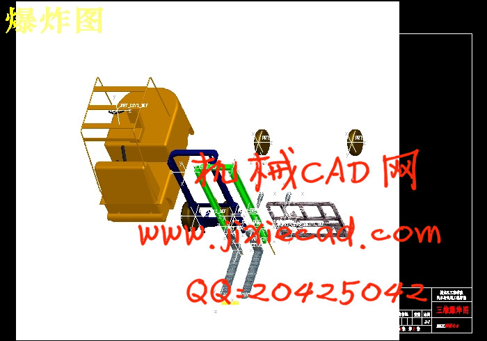
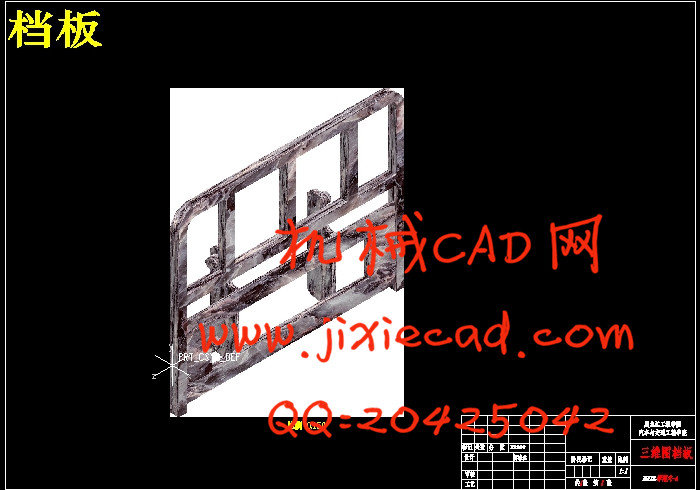
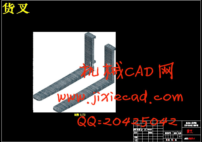
设计简介
摘 要
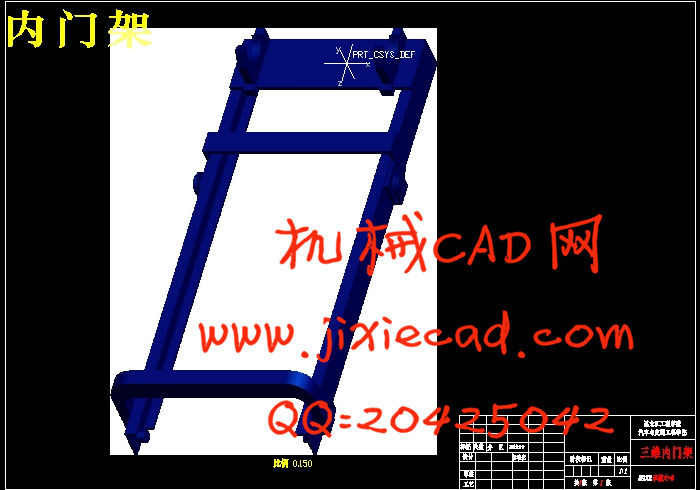
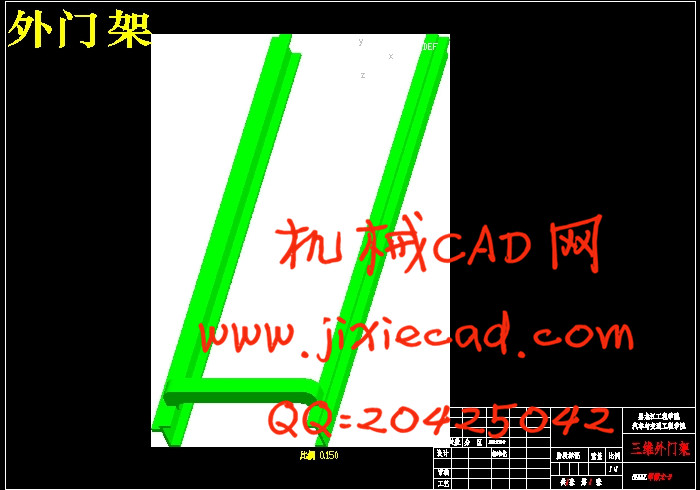
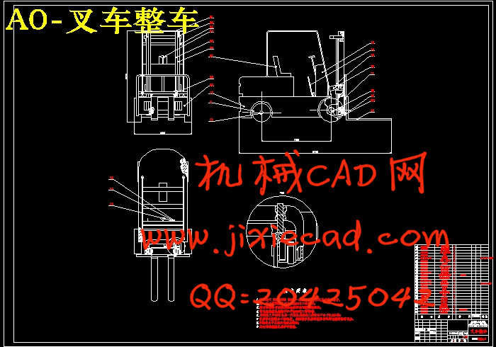
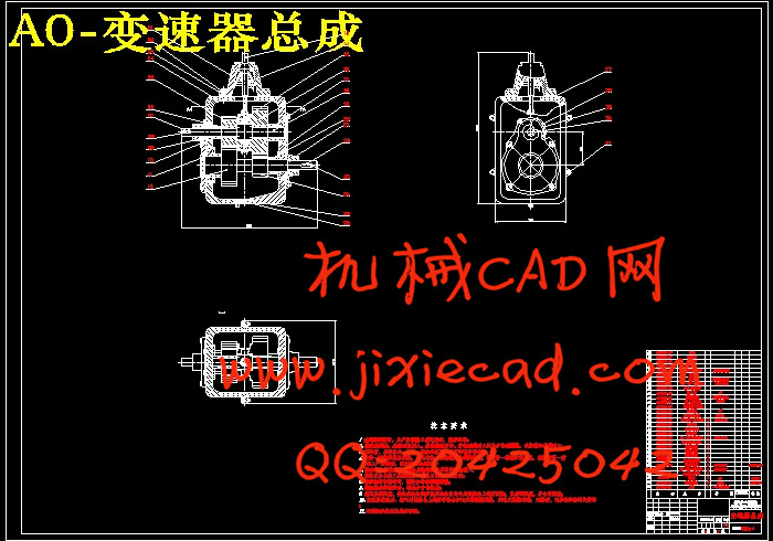
平衡重式电动叉车由于其操作控制简便、灵活,其操作人员的操作强度要求相对内燃叉车而言轻很多,广泛使用在国民经济的各个部门,其电动转向系统、加速控制系统、液压控制系统以及刹车系统都由电信号控制大大降低了操作人员的劳动强度,这样一来对于提高其工作效率以及工作的准确性有非常大的帮助且相较于内燃叉车电动车辆的低噪音、无尾气排放的优势也得到许多用户的许可。如何更好的发挥其优势来取代内燃叉车,对环保有重大意义。本课题研究运用计算机仿真技术对电动叉车进行虚拟设计,在产品制造之前将运用AutoCAD完成平衡重式电动叉车变速器、货叉及整车装配的二维绘制,为之后的Pro/E软件的三维图绘制做铺垫,然后将用Pro/E软件对平衡重式电动叉车的各个零件进行三维绘制并进行整车装配,为之后的ANSYS分析建立三维模型,最后将运用ANSYS软件进行仿真研究,就可以发现并更正设计缺陷,完善设计方案,缩短开发周期,提高设计质量和改善,为生产实际提供理论支持。
关键词:电动叉车;变速器;货叉;三维建模;有限元分析
ABSTRACT
Counterbalanced electric forklift operation control because of its simple, flexible, and its operator's operations in terms of strength requirements are relatively much lighter internal combustion forklifts, widely used in various sectors of national economy, the electric power steering system, the speed control system, hydraulic control system and control the brake system greatly reduces the signal by the operator's labor intensity, so that its work for improving the efficiency and accuracy of the work has a very big help, and internal combustion forklift electric vehicles compared to the low noise, no exhaust emissions advantage by many users permission. How to better play to their strengths instead of internal combustion forklifts, of great importance to environmental protection. This study is the use of computer simulation technology for electric forklifts for virtual design, manufacturing completed before the use of AutoCAD transmission counterbalanced electric forklift, fork and two-dimensional vehicle assembly drawing for the following Pro/E, three-dimensional map pave the way to draw, and then use the Pro / E software counterbalanced electric forklift parts for all three-dimensional drawing and make the vehicle assembly, after the ANSYS analysis for the establishment of three-dimensional model, and finally the use of ANSYS simulation software, can be found and correct design flaws and improve the design, shorten the development cycle, improve design quality and improvement, provide theoretical support for the actual production.
Key words:Electric Forklift; Transmission; Tork; Three-Dimensional Modeling; Finite Element Analysis
本设计的叉车额定起重量为2000kg,标准载荷中心距为500mm,最大起升高度为3000mm,门架前后倾角为6/12,最大起升速度(满载)为340mm/s,最大行驶速度为12Km/h,最大爬坡度为18%,最小转弯半径为2000mm,前轮胎为6.50-10-10PR,后轮胎为5.00-8-8PR。利用AutoCAD、Pro/E软件完成叉车变速器、货叉二维设计及整车三维造型、利用ANSYS软件对货叉部分关键零部件进行强度、刚度及稳定性校核。
目 录
摘 要………………………………………………………………………………I
Abstract………………………………………………………………………II
第1章 绪 论……………………………………………………………………1
1.1 选题背景、目的及意义……………………………………………………1
1.2 国内外研究现状……………………………………………………………3
1.3研究内容及研究方法………………………………………………………4
1.3.1 设计主要内容…………………………………………………………4
1.3.2 研究方法………………………………………………………………4
第 2 章 平衡重式电动叉车设计总体方案…………………………………6
2.1 叉车的定义…………………………………………………………………6
2.2 蓄电池的选择………………………………………………………………9
2.3 行走电机的选择……………………………………………………………10
2.4 本章小结……………………………………………………………………11
第3章 变速箱设计……………………………………………………………12
3.1变速箱的结构方案…………………………………………………………13
3.1.1中心距的确定…………………………………………………………13
3.1.2齿轮参数确定…………………………………………………………13
3.1.3 齿轮齿数确定………………………………………………………14
3.1.4齿轮其他基本几何参数………………………………………………14
3.2 对中心距A进行修正………………………………………………………14
3.3齿轮校核……………………………………………………………………15
3.3.1齿轮折断………………………………………………………………15
3.3.2齿面点蚀………………………………………………………………16
3.3.3齿面胶合………………………………………………………………16
3.3.4齿轮弯曲强度计算……………………………………………………17
3.3.5齿轮接触应力计算……………………………………………………17
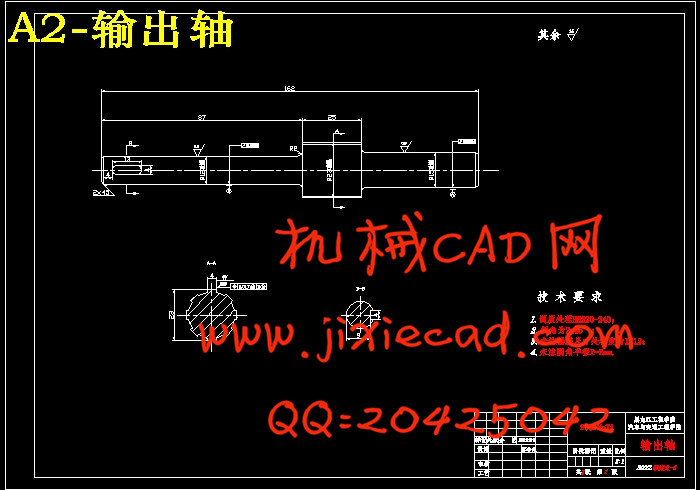
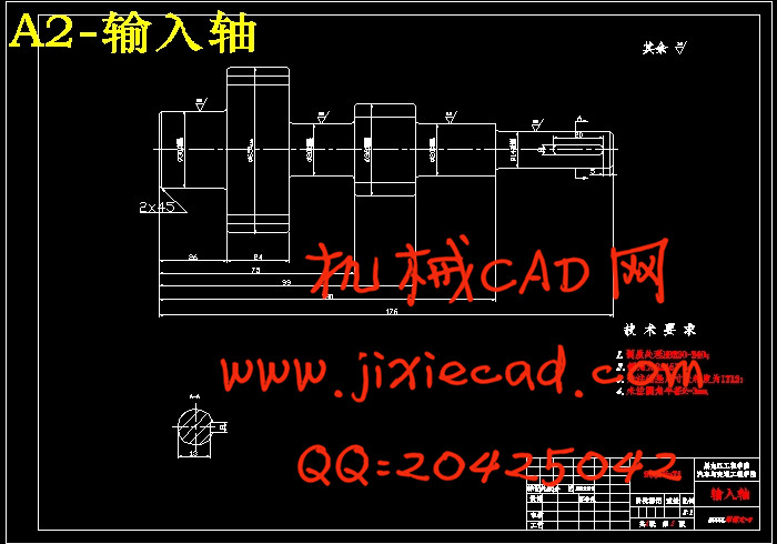
3.4 轴设计………………………………………………………………………18
3.4.1 初选轴的直径………………………………………………………18
3.4.2 轴的刚度验算………………………………………………………18
3.4.3 轴的强度计算………………………………………………………21
3.4.4 变速器轴承的选择…………………………………………………22
3.5 本章小结……………………………………………………………………25
第4章 货叉、门架、叉架及整车建模……………………………………26
4.1 Pro/E软件简介……………………………………………………………26
4.2货叉尺寸计算………………………………………………………………27
4.3车体尺寸设计………………………………………………………………29
4.3.1车体设计内容…………………………………………………………29
4.3.2车体设计步骤…………………………………………………………30
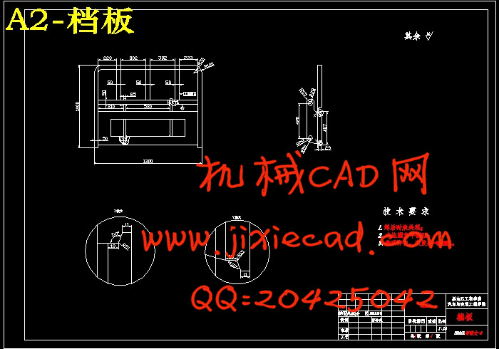
4.4档板尺寸设计………………………………………………………………31
4.4.1特征建模思想…………………………………………………………31
4.4.2起升系统的装配………………………………………………………33
4.4.3元件的约束类型及其放置参照………………………………………33
4.4.4货叉的建立……………………………………………………………34
4.4.5叉架的建立……………………………………………………………35
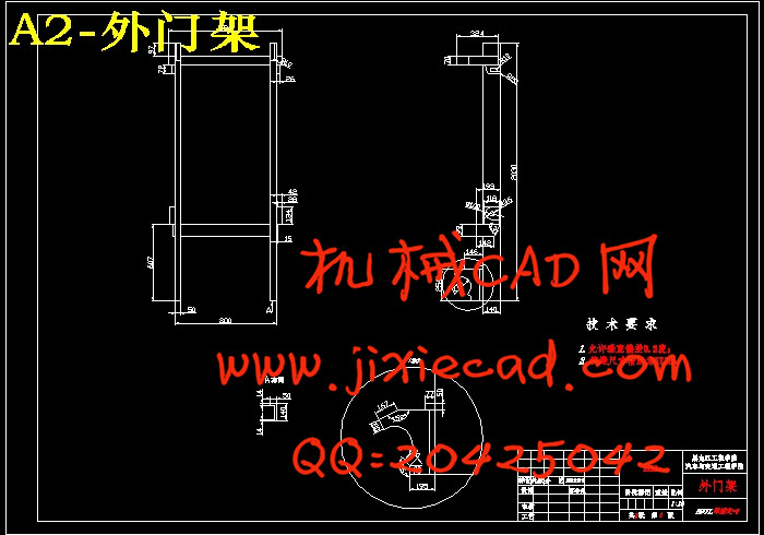
4.4.6外门架的建立…………………………………………………………35
4.4.7 Pro/E整机装配图……………………………………………………35
4.5叉车稳定性计算……………………………………………………………36
4.6 本章小结……………………………………………………………………37
第5章 主要零部件有限元分析………………………………………………38
5.1 ANSYS简介…………………………………………………………………38
5.1.1 ANSYS的主要技术特点……………………………………………38
5.1.2 软件功能简介………………………………………………………39
5.2 ANSYS与Pro/E的接口技术……………………………………………39
5.2.1 使用ANSYS提供的图形接口………………………………………39
5.2.2 Pro/E与ANSYS的连接方法……………………………………40
5.3对货叉进行有限元分析……………………………………………………41
5.3.1货叉的有限元分析……………………………………………………41
5.4 本章小结……………………………………………………………………44
结论…………………………………………………………………………………45
致谢…………………………………………………………………………………46
参考文献……………………………………………………………………………47
附录…………………………………………………………………………………49


