设计简介
摘 要
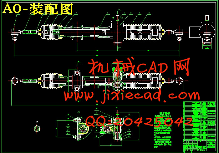
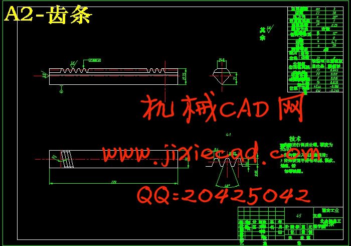
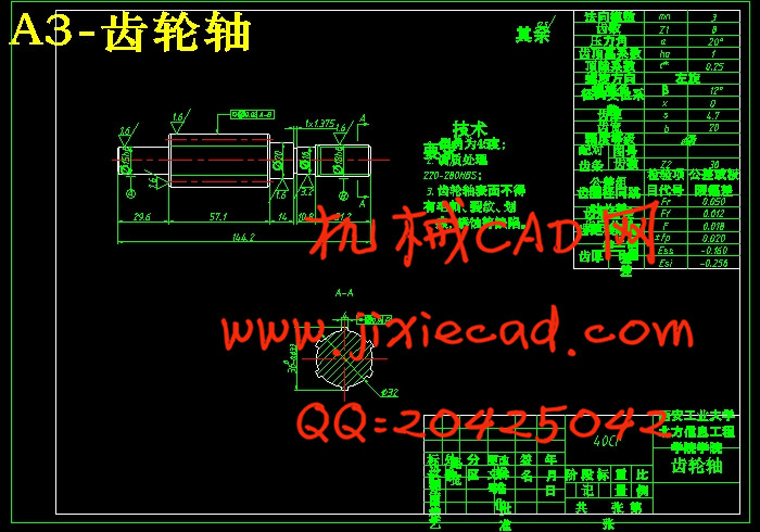
汽车的转向系统的性能是汽车的主要性能之一,转向性能直接影响到汽车的操纵稳定性,它对于确保车辆的安全行驶、减少交通事故以及保护驾驶员的人身安全、改善驾驶员的工作条件起着重要的作用。齿轮齿条式转向器是将司机对转向盘的转动变为齿条沿轴向移动,并按照一定的角传动比和力传动比进行传递的机构。其基本结构是一对相互啮合的齿轮和齿条,转向轴带动小齿轮旋转时,齿条便做直线运动,同时靠齿条带动横拉杆就可使转向轮转向,所以这是一种最简单的转向器,它具有结构简单紧凑、质量轻、刚度大、转向灵敏、制造容易、成本低,正逆效率高一级便于布置等优点,而且特别适用在独立式麦弗逊式悬架配用,因此目前它在轿车和微型、轻型货车上得到了广泛应用。
关键词:齿轮齿条;转向器;汽车
Automobile Gear Rack Type Steering System Design
Abstract
The function of automotive steering system is one of the most important functions. It can influence the stability in manipulation, also plays an important role in ensuring safe driving, reducing traffic accident, protecting driver’s safety and improving driver’s work condition.Rack and pinion steering gear is the driver of the steering wheel along the axis of rotation into a mobile rack and gear ratio according to a certain angle and force transmission ratio for delivery of the body. The basic structure is a pair of mutually meshing gears and rack pinion steering drive shaft rotates, the rack will be a straight line, while driven by the rack to tie rod steering wheel can turn, so this is one of the most simple the steering, it has simple structure, light weight, stiffness, steering is sensitive, easy manufacturing, low cost, high efficiency and a convenient forward and reverse layout, etc. and especially for the independent suspension with McPherson-type , so now it is in the car and micro, light truck has been widely used.
Key Words: rack-and pinion; steering gear; automobile
目 录
1 绪论 1
1.1 汽车齿轮齿条式转向系统的概述 1
1.2 齿轮齿条式转向系统的发展概况 1
1.3 齿轮齿条式转向器背景、研究意义及国内外发展情况 1
1.4 汽车齿轮齿条式转向原理及基本特性 3
2 汽车齿轮齿条式转向系统的类型、组成及工作原理 5
2.1 机械转向系统的组成 5
2.1.1 转向操纵机构的功能与组成 5
2.1.2 转向盘 5
2.1.3 转向轴和转向管柱 6
2.1.4 安全保护装置 6
2.2 机械转向系统的工作原理 7
2.3 械转向系统的优缺点 8
3 齿轮齿条式转向器设计方案的选择 9
4 齿轮齿条式转向系的设计 12
4.1 齿轮齿条式转向器的设计 12
4.1.1齿轮齿条式转向器的主要元件 12
4.1.2 转向传动比 13
4.1.3 齿轮齿条式转向器的安装 13
4.1.4 齿轮齿条式转向器的设计要求 13
4.2 齿轮齿条式转向系主要参数的确定 13
4.2.1 转向节原地转向力矩MR的计算 13
4.2.2 转向盘手力Fh的计算 14
4.2.3 转向盘手力矩
4.2.4 角传动比
4.2.5 力传动比
4.2.6 梯形臂长度L的计算 15
4.2.7 转向轮侧偏角的计算 15
4.3 齿轮齿条式转向器设计计算 16
4.3.1 主要设计参数的选择 16
4.3.2 齿轮轴和齿条的设计计算 16
4.4 齿轮齿条式转向器转向横拉杆的运动分析 22
4.5 齿轮齿条传动的受力分析 22
4.6 齿轮轴的强度校核 23
4.6.1轴的受力分析 23
4.6.2 判断危险剖面 23
4.6.3 轴的弯扭合成强度校核 24
4.6.4 轴的疲劳强度安全系数校核 24
4.7 齿轮轴轴承的校核 26
4.7.1 求比值 26
4.7.2 初步计算当量动载荷
4.7.3 根据式,计算轴承应有的额定动载荷值 27
4.7.4 6204轴承的校核 27
4.8 间隙调整弹簧的设计计算 28
4.8.1 根据工作情况及具体条件选定材料,并查取其力学性能数据 28
4.8.2 弹簧丝直径
4.8.3 弹簧工作圈数和自由高度的设计计算 28
4.8.4 验算稳定性 29
4.8.5 检查
4.8.6 弹簧几何参数和结构尺寸的确定 29
4.8.7 疲劳强度和静应力强度的验算 29
4.8.8 弹簧振动的验算 32
5 结论 32
参考文献 33
致 谢 34


