设计简介
摘 要
论文完成了汽车发动机箱体的多个孔的专用机床的设计,要求一次装夹完成驱动桥壳孔的加工,保证孔位置精度和其他加工要求。通过对原始数据(材料,尺寸及加工要求)的分析计算,确定了刀具的切削用量,机床配置形式,并计算出主轴的切削功率和转速,合理选择机床的通用部件及设计相配套的夹具。采用卧式组合机床进行零件的加工,配以转角液压缸夹紧,提高工件的装夹速度。设计的组合机床提高了机床加工精度,保证被加工零件的加工要求,且工作稳定,操作方便,减少了加工时间,提高了工作效率。
关键词:组合机床;专用夹具;驱动桥壳;零件
ABSTRACT
Thesis completed automobile engine box of a plurality of holes special machine design, requirements to complete a fixture drive axle hole machining, hole locations to ensure the accuracy and other processing requirements. The original data (material, size, and processing requirements) analysis and calculation to determine the cutting tool, machine tool configurations, and calculate the spindle cutting power and speed, a reasonable choice of common components and design tools supporting the fixture. A horizontal combination machine for machining, hydraulic cylinder with corner clamp, improve workpiece clamping speed. The combination tool designed to improve the machining accuracy, and ensure the processing requirements of parts to be machined, and job stability, easy to operate, reducing the processing time, improve work efficiency.
Keywords: combination machine; special fixtures; drive axle housing; Parts
目录
摘 要 III
ABSTRACT IV
前 言 V
1 绪论 1
1.1组合机床的组成及特点 1
1.2多轴箱设计介绍 1
1.3液压系统 2
2 零件加工工艺分析 5
2.1零件的作用 5
2.2零件工艺分析 5
2.3工艺规程设计 5
2.4本工序工艺方案的拟订 6
3 切削用量的确定 6
3.1加工内容及切削用量参数表 7
3.2确定切削力F(N)、切削转矩T(N•mm)、切削功率P(kw) 7
4 组合机床总体设计 16
4.1被加工零件工序图 16
4.1.1 被加工零件工序图的作用与内容 16
4.1.2 绘制被加工零件工序图的规定及注意事项 16
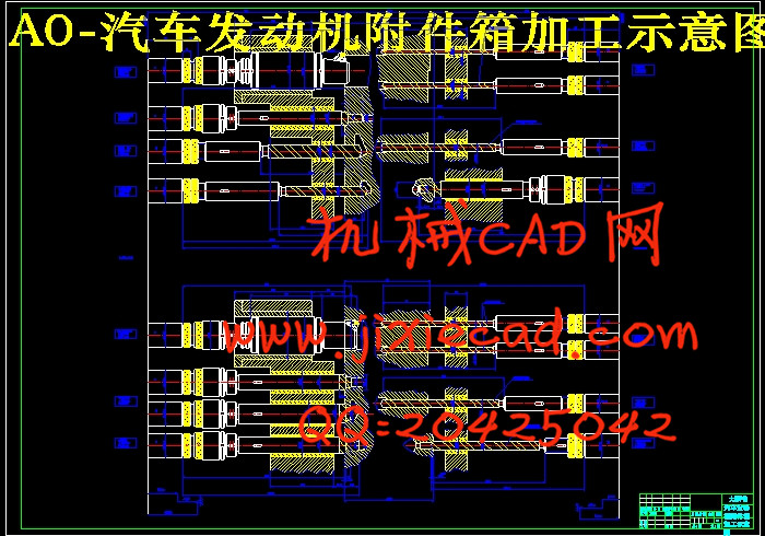
4.2加工示意图 17
4.3机床联系尺寸总图 20
4.3.1 机床联系尺寸总图的作用于内容 20
4.3.2绘制机床联系尺寸之前应确定的主要内容 20
4.3.3 机床分组 22
4.4机床生产率计算卡 22
4.4.1理想生产率Q 22
4.4.2实际生产率Q1 23
4.4.3机床负载率η负 23
5 专用夹具设计 24
5.1制定设计方案 25
5.1.1确定夹紧方式,设计夹紧机构。 25
5.1.2夹具夹紧力分析 26
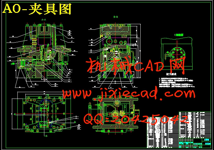
5.2绘制夹具装配总图 26
图5.1夹具装配图 27
5.3绘制夹具零件图 28
6 专用多轴箱的设计 29
6.1多轴箱的功用及分类 29
6.2专用多轴箱的组成 29
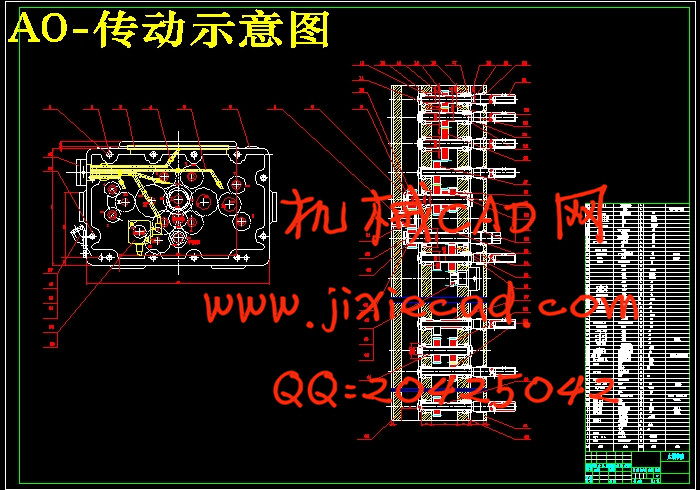
6.3专用多轴箱的传动系统设计 29
6.4专用多轴箱的设计 31
6.5 润滑泵的选择 33
6.6其他相关部件的选择 34
7 结论 36
致谢 37
参考文献 38


