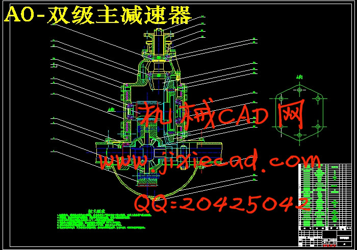
设计简介
摘要
驱动桥作为汽车四大总成之一,它的性能的好坏直接影响整车性能,而对于载重汽车显得尤为重要。当采用大功率发动机输出大的转矩以满足目前载重汽车的快速、重载的高效率、高效益的需要时,必须要搭配一个高效、可靠的驱动桥。所以采用传动效率高的双级减速驱动桥已成为未来重载汽车的发展方向。
本文参照传统驱动桥的设计方法进行了载重汽车驱动桥的设计。本文首先确定主要部件的结构型式和主要设计参数;然后参考类似驱动桥的结构,确定出总体设计方案;最后对主,从动锥齿轮,差速器圆锥行星齿轮,半轴齿轮,全浮式半轴和整体式桥壳的强度进行校核以及对支承轴承进行了寿命校核。本文不是采用传统的双曲面锥齿轮作为载重汽车的主减速器而是采用弧齿锥齿轮。
关键词:载重汽车;驱动桥;双级主减速器;全浮式半轴
Abstract
As a vehicle drive axle assembly of one of the four, and its performance will have a direct impact on vehicle performance, and it is particularly important for trucks. When using high-power engine torque output of large trucks to meet the current fast, heavy-duty high-efficiency, cost-effective and necessary, must be with an efficient, reliable bridge driver. Therefore, efficient use of transmission of a double-stage driver slow down the bridge has become a heavy-duty motor vehicles in the future development direction.
In this paper, in the light of the traditional design of the drive axle of the truck driver for the design of the bridge. This article first identified the major components of the structure and main design parameters; then a similar reference to the drive axle of the structure to determine the overall design of the program; on the final owner, Gear Driven cone, cone differential planetary gear, axle gear, the all-floating Half-bridge and the overall strength of the shell to carry out verification as well as support for the life of bearing checking. This article is not a traditional double-bevel gear surface as the main reducer truck instead of using the spiral bevel gear, as a hope that this will continue to study this issue.
Keyword truck driver bridge double-stage bridge slowdown spiral bevel gear
目 录
摘要 I
Abstractb Ⅱ
第1章 绪论 1
第2章 驱动桥总成的结构型式 4
2.1 驱动桥总体方案的确定 4
2.1.1 非断开式驱动桥的结构分析 4
2.1.2 断开式驱动桥的结构分析 5
2.2 本设计驱动桥结构形式的确定 6
第3章 主减速器 8
3.1 主减速器的结构形式 8
3.1.1 主减速器的齿轮类型 8
3.1.2 主减速器主从动锥齿轮的支承形式 8
3.2 主减速器的基本参数选择与设计 9
3.2.1 主减速比的确定 9
3.2.2 主减速器计算载荷的确定 10
3.2.3 主减速器基本参数的确定 12
3.2.4 主减速器传动齿轮的几何尺寸计算 13
3.2.5主减速器轴承的选择 14
3.2.6 主减速器齿轮的材料及热处理 19
3.2.7 主减速器传动齿轮的强度校核 23
第4章 差速器 23
4.1 对称式圆锥行星齿轮差速器的设计 23
4.1.1 差速器齿轮基本参数的确定 23
4.1.2 差速器齿轮的几何尺寸的确定 23
4.2 差速器齿轮的强度校核 24
第5章 驱动半轴设计 26
5.1 全浮式半轴的杆部直径的初选 26
5.2 全浮式半轴的强度校核 26
5.3 半轴花键的强度校核 26
第6章 驱动桥桥壳 28
6.1 桥壳的结构形式 28
6.1.1 整体式桥壳结构形式分析 28
6.1.2 铸造整体式桥壳结构形式分析 28
6.1.3 钢板冲压焊接整体式桥壳 28
6.1.4 钢管扩张成形整体式桥壳 29
6.2 桥壳的受力分析与强度校核 29
6.2.1 桥壳的静弯曲应力计算 29
6.2.2 在不平路面冲击载荷作用下桥壳的强度校核 30
6.2.3 汽车以最大牵引力行驶时的桥壳强度校核 31
6.2.4 汽车紧急制动时的桥壳强度校核 33
结论 35
致谢 36
参考文献 37


