设计简介
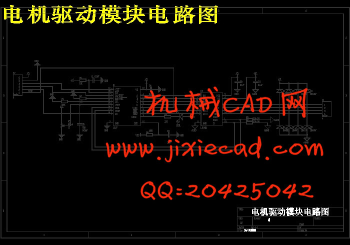
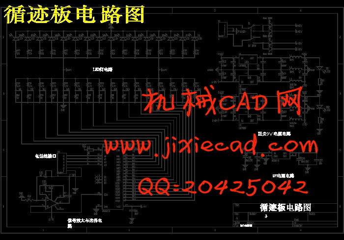
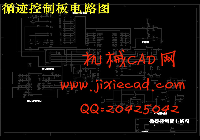
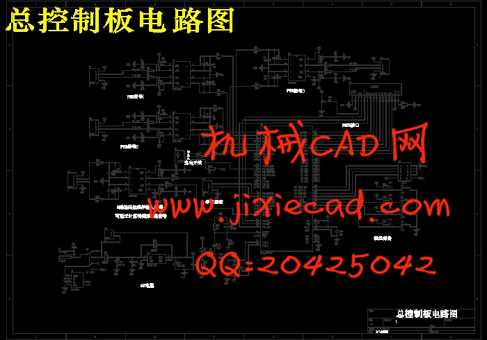
摘 要:本机器人控制系统由中央处理单元模块、循迹采样模块与电机驱动模块等组成。中央处理单元模块由AVR8位微处理器ATMEGA128、ATMEGA16为主控芯片,通过循迹采样模块采集信号并处理,利用串口通信将信号传给中央处理单元,由中央处理单元根据信号控制机器人伺服电机的运转状态,从而实现对机器人运动状态的控制。电机驱动电路采用四通道集成芯片L297和L298。通过循迹技术来实现机器人的运动路径和运动位置的判定。循迹部分采用光敏电阻接收发光二级管经过物体反射回来的光从而实现机器人按照预定轨迹移动。经试验证明,该机器人控制系统能较好完成任务。
关键词:机器人控制系统;循迹;ATMEGA128;光敏电阻;
Abstract: The robot control system consists of a central processing unit module, a tracking sampling module and the motor driver module. A central processing unit module for the master chip microprocessor from AVR8 of ATMEGA128, ATMEGA16 collection signal by tracking the sampling module and processing, the use of serial communication signals to the central processing unit, by a central processing unit according to the signal to control the robot servo motor operating state, in order to achieve the control of the state of motion of the robot. Motor drive circuit using four-channel chip L297 and L298.By tracking technology to achieve the determination of the path of movement and the movement position of the robot..The tracking part photoresistor receiving a light emitting diode, the light reflected by the object in order to achieve the robot moves in accordance with a predetermined trajectory. The test proved that the robot control system can better complete the task.
Key words: Robot control system; tracking; ATmega128; Guangmin Resistance;
目 录
摘 要 1
关键字 1
1前言 2
2总体方案设计 2
2.1总体方案简述 2
2.2各模块论证与选择 3
2.2.1中央处理模块 3
2.2.2直流电机及其驱动模块 3
2.2.3循迹模块 5
2.2.4速度检测模块 5
2.2.5通信模块 6
3硬件部分设计 8
3.1中央处理模块 8
3.2直流电机及其驱动模块 10
3.3循迹模块 11
3.3.1循迹原理分析 11
3.3.3AD采样芯片简介 12
3.4避障模块 13
3.5测速模块 14
3.6电源模块 15
3.7输入和输出显示模块 16
3.7.1模块分析 16
3.7.2按键消抖 16
3.8硬件抗干扰措施 17
3.9印制电路板可靠性和抗干扰设计 17
4算法的方案论证 18
4.1循迹板采集算法 18
4.2控制算法 18
4.2.1总控制方案的确定 18
4.2.2PID算法简介 19
4.2.3模糊控制介绍 20
4.3方向控制 21
4.3.1PID算法设计 21
4.3.2PID控制算法的具体实现 22
4.3.3滤波算法介绍 23
5软件部分设计 25
5.1程序流程图 25
5.1.1主控板程序流程图 25
5.1.2循迹控制板程序流程图 26
5.1.3路径偏差计算流程图 27
5.2PWM产生 28
5.3通信模式的选择 29
5.3.1USART简介 30
5.3.2USART寄存器说明与选择 31
6开发与调试 32
7结论 33
参考文献 33
致谢 34
附录 35
附录1 主控板程序代码 36
附录2 循迹控制板程序代码 53


