设计简介
摘 要
随着社会的发展和人们生活水平的不断提高,人们对汽车的要求已不仅仅局限于性能、成本,而是越来越多的要求现代汽车更加安全,更加环保,更加人性化。而同时,新车款型也必须符合最新的规定,这就导致了新技术不断得到应用。作为汽车的三大安全件之一,汽车照明系统是最主要的主动式安全装置,对传统汽车照明系统的改进和创新也日益成为全世界汽车厂商研究的热点问题。为此,设计了以单片机为核心,实现汽车前照灯防炫目的系统的控制。
前照灯防眩目系统主要有硬件和软件俩部分组成。硬件部分主要有电位器,单片机和舵机。电位器的电阻值可以变化,可以当作信号。单片机是控制器,把电位器传来的信号转换成舵机能识别的信号。舵机是执行器,它接收到单片机的信号后可以转动相应的角度。系统工作方式是电位器把信号传给单片机,单片机经过处理把信号转换后传给舵机。软件方面就是先把单片机的各个寄存器设置好,再把接受信号的AD口设置好,还有是控制舵机的PWM输出口。最后根据硬件把软件的各个程序段连接起来,使其正常工作。此设计中的介绍了基于STC12C4052AD单片机的汽车前照灯防炫目控制的设计。
关键词:前照灯;防炫目;ST12C4052AD;舵机;调试
ABSTRACT
With the development of the society and the continuous improvement of people's living standard, people on the requirements of the car has not only confined to performance, cost, but more and more requirements modern car safer, more environmental protection and more human. And at the same time, the new car should also must comply with the latest regulation, this has led to a new technology to get the application. As the big three auto safety thing, automobile lighting systems is one of the main active safety device, to the traditional automobile lighting system improvement and innovation also has become a hot spot in the study of the world automobile manufacturers. Therefore, the single-chip design as the core, and realize the automobile lamps glaring system control.
The system is mainly a headlamp blinding hardware and software both parts. Hardware mainly potentiometer, SCM and steering gear. Resistance can change the potentiometer, can be as a signal. A single chip computer is the controller, the signal conversion from potentiometer into steering gear can identify signal. The steering gear is the implementation, it receives SCM signal after can turn the corresponding Angle. The system is the signal potentiometer working way to microcontroller, SCM processing after the signal conversion to the steering gear. Software is the first chip set, each register to receive signals mouth set good, and the AD is steering gear control PWM outlets. Finally, according to the hardware of software for each program link up, make its normal work. This design is introduced STC12C4052AD based on the chip automobile lamps and glaring the design of the control.
Key words: Headlamps ; Prevent Glaring; STC12C4052AD; Steering gear;Debugging
目 录
摘要………………………………………………………………………………………I
Abstract…………………………………………………………………………………II
第1章 绪论………………………………………………………………………………1
1.1 汽车自适应照明的产生………………………………………………………1
1.2 自适应系统的功能及简介……………………………………………………2
1.3 汽车自适应的系统的国内外发展………………………………………………2
1.4 课题主要研究的内容……………………………………………………………3
第2章 系统整体方案设计………………………………………………………4
2.1 需求分析…………………………………………………………………4
2.2系统构成…………………………………………………………………5
2.3 系统计算理论基础………………………………………………………………5
2.4 本章小结…………………………………………………………………………6
第3章 系统的硬件结构设计………………………………………………………7
3.1 系统单片机的选择………………………………………………………………7
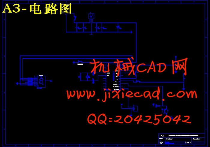
3.2 传感器电路设计…………………………………………………………………10
3.3 系统舵机及电路的设计………………………………………………………… 12
3.4 自动变光模块的设计…………………………………………………………15
3.5 系统电源稳压电路…………………………………………………………16
3.5.1 7805芯片…………………………………………………………17
3.5.2 适配器的选择………………………………………………………17
3.5.3电容……………………………………………………………18
3.6 本章小结…………………………………………………………………………19
第4章 系统的软件结构设计………………………………………………………20
4.1系统程序编写原理………………………………………………………20
4.1.1 系统舵机程序………………………………………………………20
4.1.2系统AD转换程序………………………………………………………22
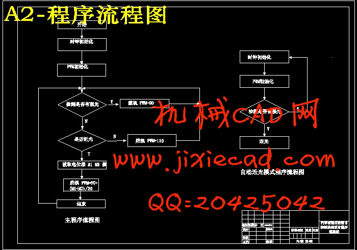
4.2主程序流程图……………………………………………………………………24
4.3 本章小结………………………………………………………………………25
第5章 制作与调试……………………………………………………………………26
5.1 硬件的制作……………………………………………………………………26
5.1.1 焊接时布线及其注意事项…………………………………………………26
5.1.2硬件的整体焊接……………………………………………………………29
5.2 硬件调试…………………………………………………………………………30
5.2.1 单片机各口输出信号…………………………………………………… 30
5.2.2 电位计、舵机和光敏电阻的调试…………………………………………32
5.3 软件调试…………………………………………………………………………35
5.4 本章小结…………………………………………………………………………39
结论………………………………………………………………………………………38
参考文献…………………………………………………………………………………40
致谢………………………………………………………………………………………41
附录………………………………………………………………………………………42
附录A 英文文献与中文参考译文…………………………………………………42
附录B 整机原理图…………………………………………………………………48
附录C实物效果图…………………………………………………………………51
附录D材料清单……………………………………………………………………53
附录E 源程序………………………………………………………………………54


