设计简介
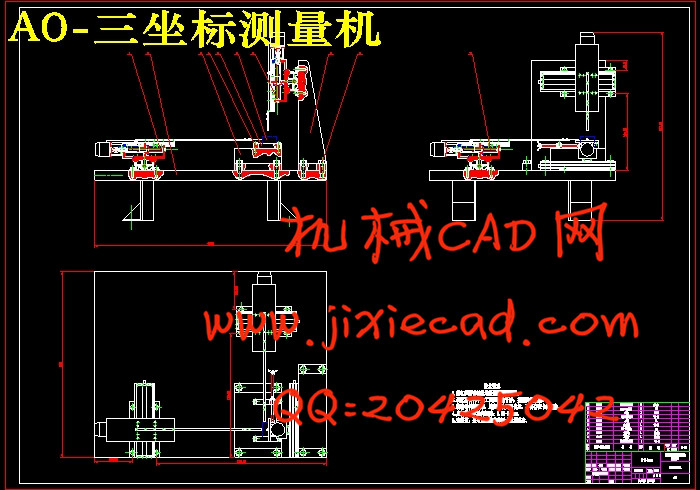
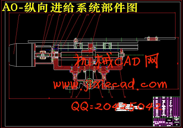
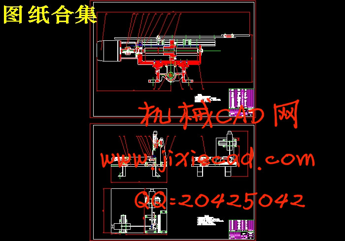
摘要:从60年代初发明到现在,三坐标测量机(CMM)在制造业得到世界范围广泛应用,成为3D检测工业标准设备。三坐标测量技术得到迅速发展,而配套检测软件的发展,更是突飞猛进。最早的三坐标测量机只能显示XYZ坐标,而目前的各种检测软件几乎可以解决用户的绝大部分问题。软件日益成为影响用户使用好坏的关键所在。CMM测量软件发展趋势,对于传统的三坐标测量机检测来说,通常是设计部门提供二维图纸,检验部门根据图纸对工件进行尺寸及形位公差的检测。随着三维CAD软件的应用,越来越多的技术部门使用三维CAD建模技术进行设计。因此,各坐标机厂家纷纷推出了基于三维CAD技术的测量软件,直接将客户设计好的三维CAD模型导入测量软件进行检测。这样做的优点非常明显,不需要额外的图纸,理论值可以直接捕获,更可以进行测量仿真,测头干涉检查等,所以,受到用户的一致好评。基于CAD的测量成为目前三坐标测量软件的发展热点。
关键词 三坐标测量机 传感器 三维 传动装置
Abstract:Invents from the beginning of the 60's to present, coordinate measuring machines (CMM) obtains the worldwide scale widespread application in the manufacturing industry, becomes the 3D examination industry standard equipment. Three coordinates survey technology obtains the rapid development, but the necessary examination software development, is progresses by leaps and bounds. The earliest coordinate measuring machines only can demonstrate the XYZ coordinates, but the present each kind of examination software may solve user's major part problem nearly. The software becomes the influence user use quality the key to be at day by day. The CMM survey software trend of development, regarding the traditional coordinate measuring machines examination, usually is designs the department to provide the two-dimensional blueprint, the inspection department carries on the size and the shape position common difference examination according to the blueprint to the work piece. Along with the three dimensional CAD software application, the more and more many technical department uses the three dimensional CAD modeling technology to carry on the design. Therefore, various coordinates machine factory has promoted in abundance based on the three dimensional CAD technology survey software, the three dimensional CAD model which designs the customer inducts directly surveys the software to carry on the examination. Does this the merit is extremely obvious, does not need the extra blueprint, the theoretical value may catch directly, may carry on the survey simulation, the gauge head interference inspection and so on, therefore, receives the user the consistent high praise. Survey the software based on the CAD survey into at present three coordinates the development hot spot.
Key words Coordinate measuring machines Sensor Three dimensional Transmission device
目 录
摘要………………………………………………………………………………I
Abstract………………………………………………………………………II
1 绪论…………………………………………………………………………1
1.1 三坐标测量机的应用与发展…………………………………………1
1.2 三坐标测量机测量原理………………………………………………5
1.2.1 三坐标测量机的组成…………………………………………7
1.2.2 三坐标测量机的结构特点……………………………………7
1.3 设计要求………………………………………………………………8
2 三坐标测量机的总体设计方案……………………………………8
2.1 设计任务和内容………………………………………………………8
2.2 总体设计方案拟订……………………………………………………9
2.2.1 三坐标测量机机械部分设计…………………………………9
2.2.2 三坐标测量机电路部分设计………………………………10
2.3 参数的确定……………………………………………………………18
3 三坐标测量进给系统的设计计算………………………………19
3.1 动机的选择计算……………………………………………………19
3.1.1 调速电动机的容量的计算…………………………………19
3.1.2 步进电动机的概述…………………………………………19
3.1.3 步进电动机的容量的计算…………………………………20
3.2 轴概述 ………………………………………………………………20
3.2.1 轴的用途……………………………………………………20
3.2.2 轴的材料……………………………………………………21
3.2.3 轴的材料……………………………………………………21
3.3 轴的结构设计………………………………………………………21
3.3.1 拟定轴上零件的装配方案…………………………………22
3.3.2 轴上零件的定位 ……………………………………………22
3.3.3 轴的结构设计………………………………………………23
3.3.4 初步设计轴的最小直径.............................24
3.3.5 拟定轴上零件的装配方案…………………………………25
3.3.6 根据轴向定位的要求确定轴的个段直径和长度…………26
3.3.7 轴上零件的轴向定位………………………………………27
3.3.8 确定轴上圆角和倒角尺寸…………………………………27
3.4 丝杠螺母副的选用计算……………………………………………27
3.4.1 丝杠螺母的导程的确定……………………………………27
3.4.2 确定丝杠的等效转速………………………………………27
3.4.3 丝杠的等效负………………………………………………27
3.4.4 确定丝杠所受的最大动载荷Cax……………………………27
3.4.5 临界压缩负荷Fcr……………………………………………28
3.4.6 临界转速验算………………………………………………28
3.4.7 计算轴承动载荷……………………………………………29
3.4.8 丝杠拉压振动和扭转振动的固有频率验算………………30
3.5 丝杠的扭转刚度……………………………………………………30
3.6 传动精度计算………………………………………………………31
3.7 导轨的选型及计算…………………………………………………32
3.7.1 滚动导轨的结构及配………………………………………32
3.7.2 滚动导轨副的预紧…………………………………………33
3.7.3 滚动导轨副润滑防护………………………………………33
3.8 横向伺服进给系统的设计计算(同以上方法)……………………33
3.9 纵向、横向的移动工作台的装配图(见附图1)…………………33
4 夹具的初步设计………………………………………………………34
4.1 载要…………………………………………………………………34
4.2 机床夹具的基本要求………………………………………………34
4.3 机床夹具概述………………………………………………………35
4.3.1 机床夹具的分类……………………………………………35
4.3.2 夹具的作用…………………………………………………35
4.3.3 夹具的组成…………………………………………………36
4.4 螺旋夹紧装置………………………………………………………37
4.4.1 螺旋夹紧力计算……………………………………………37
4.4.2 螺旋夹紧的自锁性能和传力系数…………………………38
4.5 螺旋夹紧机构的特点………………………………………………39
4.6 横向伺服系统和立拄的设计计算…………………………………39
结论 …………………………………………………………………………40
致谢 …………………………………………………………………………41
参考文献 …………………………………………………………………42


