设计简介
中文摘要
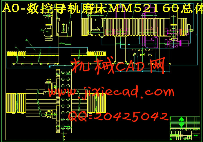
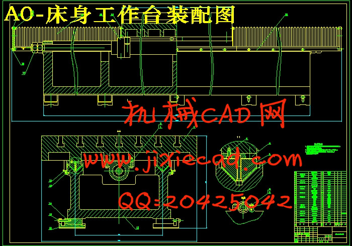
数控导轨磨床MM52160整体采用双柱式龙门框架结构,由床身、工作台、立柱、横梁、滑板、磨头等主要部件组成。M52160的主运动是周边磨头、万能磨头带动砂轮的旋转运动。机床的纵向进给由液压系统驱动工作台运动来实现,床身、工作台为双V型自定位导轨,提高了工作台运动的直线性。其中一条导轨体是横向可浮动的,补偿了由于导轨副运动摩擦发热而引起的导轨中心距的变化。水平和垂直方向的进给均由伺服电机通过滚珠丝杠螺母副驱动执行元件(横滑板和垂直滑板)运动来完成。该机床的控制系统采用主从式模块化控制结构,微机作为中央控制器,实现对进给系统控制模块、主运动速度控制模块、以及辅助系统的集中控制管理。进给系统的控制由PLC来完成。
关键词 数控导轨磨床 整体结构 控制系统
外文摘要
Title The design of Numerical control guideway grinder
Abstract
Numerical control guideway grinder MM52160 is formed of body section, workbench, upright column, beam, sliding plate and grinding head . The rotational movement of the periphery grinding head and the universal grinding head is the primary motion of this numerical control guideway grinder. The longitudinal feed is realized by the hydraulics system. The workbench is driven by a hydraulics cylinder. There are two V-mode piece of guideway on the workbench ,one of which is relocatable. So the straightness of the longitudinal feed is greatly advanced. And the same time , it can compensate the variation of the guideway’s center distance caused by friction fever. The feed movement on both horizon and vertical direction is completed by sliding plate and ball screw driven by A.C servo-actuator . The control system of this numerical control guideway grinder adopts master-slave mode and modular control structure. As a central control unit, the microcomputer centralized control and supervise the input system control module, the primary motion velocity control module, as well as the subsystem. The input system control module is controlled by a programmable logic controller. The velocity of primary motion is changed by transducer.
Keywords numerical control guideway grinder structure
control system
目 录
1 引言……………………………………………………………………4
2 机床总体方案及主要参数确定………………………………………5
2.1 机床总体方案………………………………………………………5
2.2 机床主要参数确定…………………………………………………7
3 周边磨头部件设计……………………………………………………7
3.1 运动和动力参数计算………………………………………………7
3.2 周边磨头主轴部件设计计算………………………………………8
3.3 周边磨头垂直滑板设计计算………………………………………18
4 床身工作台设计………………………………………………………20
4.1 床身工作台总体尺寸确定…………………………………………20
4.2 床身工作台导轨设计………………………………………………20
5 控制系统设计…………………………………………………………22
5.1 控制对象的描述……………………………………………………22
5.2 总体控制方案确定…………………………………………………23
5.3 电气控制系统硬件的选择…………………………………………24
5.4 控制系统程序设计…………………………………………………26
毕业设计总结………………………………………………………………33
致谢…………………………………………………………………………34
参考文献……………………………………………………………………34


