设计简介
数控相贯线切割机XY工作台部件及单片机控制设计
摘要:相贯线切割的适用对象主要是难切割材料,如高强度、高韧性材料以及精密细小和形状复杂的零件,因而数控相贯线切割在我国制造业中正发挥出巨大的优越性。
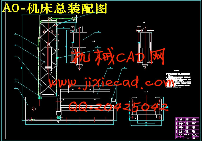
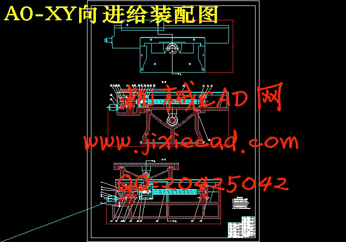
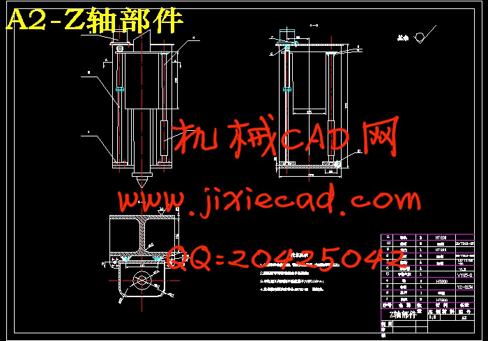
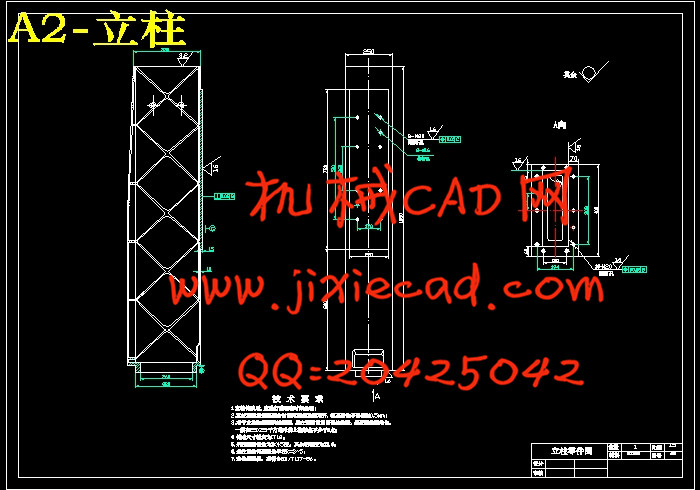
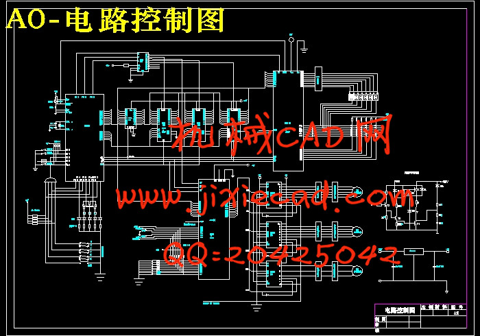
本文设计了一台单片机控制的数控相贯线切割机床,主要完成了:机床整体结构设计,Z轴、XY轴的结构设计计算、滚珠丝杠、直线滚动导轨的选择及其强度分析;以步进电机为进给驱动的驱动系统及其传动机构的分析设计计算;以89C51为主控芯片的数控系统硬件电路设计、系统初始化设计及系统软件方案设计和步进电机的控制程序设计。
关键词 CNC,相贯线切割机床,XY工作台,单片机
300 × 400 CNC laser cutting machine XY
table parts and SCM control design
ABSTRACT:Laser cutting machine tool was usually used for the hard-cutting material, such as high-strength material, high precision ductile materials, and smart and complicated components. So, CNC laser cutting has been playing an important role in China's manufacturing industry.
This paper describes the design of a SCM-controlled CNC laser cutting machine tools. More attention was paid on the overall machine design, Z axis, XY axis in the design, ball-screw and the choice of linear motion guide and intensity analysis; the drive system into which stepper motor was put and the analysis of the drive system design; 89C51 chip was mainly used for the design of hardware circuit, the design of system initialization and the design of stepper motor’s controlling program.
Key words CNC, laser cutting machine tools, XY table ,Single chip microcomputer
目 录
第一章 绪论…………………………………………………………………… 1
1.1相贯线技术概述………………………………………………………………… 1
1.2相贯线切割机的应用…………………………………………………………… 1
1.3设计任务……………………………………………………………………… 1
1.4总体设计方案分析…………………………………………………………… 2
第二章 机械部分XY工作台及Z轴的基本结构设计…………………………4
2.1 XY工作台的设计………………………………………………………………4
2.1.1主要设计参数及依据………………………………………………………4
2.1.2 XY工作台部件进给系统受力分析……………………………………… 4
2.1.3初步确定XY工作台尺寸及估算重量…………………………………… 4
2.2 Z轴随动系统设计………………………………………………………………5
第三章 滚珠丝杠传动系统的设计计算………………………………………… 7
3.1 滚珠丝杠副导程的确定……………………………………………………… 7
3.2 滚珠丝杠副的传动效率……………………………………………………… 7
第四章 直线滚动导轨的选型…………………………………………………… 9
第五章 步进电机及其传动机构的确定………………………………………… 11
5.1 步进电机的选用……………………………………………………………… 11
5.1.1 脉冲当量和步距角……………………………………………………… 11
5.1.2步进电机上起动力矩的近似计算……………………………………… 11
5.1.3确定步进电机最高工作频率…………………………………………… 12
5.2齿轮传动机构的确定………………………………………………………… 12
5.2.1传动比的确定…………………………………………………………… 12
5.2.2齿轮结构主要参数的确定……………………………………………… 12
5.3步进电机惯性负载的计算…………………………………………………… 13
第六章 传动系统刚度的确定…………………………………………………… 15
6.1 根据工作台不出现爬行的条件来确定传动系统的刚度…………………… 15
6.2根据微量进给的灵敏度来确定传动系统刚度……………………………… 15
第七章 消隙方法与预紧………………………………………………………… 17
7.1消隙方法……………………………………………………………………… 17
7.1.1偏心轴套调整法………………………………………………………… 17
7.1.2锥度齿轮调整法………………………………………………………… 18
7.1.3双片齿轮错齿调整法…………………………………………………… 18
7.2预紧…………………………………………………………………………… 19
第八章 控制系统设计…………………………………………………………… 20
8.1 确定机床控制系统方案……………………………………………………… 20
8.2 主要硬件配置………………………………………………………………… 20
8.2.1主要芯片选择…………………………………………………………… 20
8.2.2 主要管脚功能…………………………………………………………… 20
8.2.3 EPROM的选用…………………………………………………………… 21
8.2.4 RAM的选用……………………………………………………………… 22
8.2.5 89C51存储器及I/O的扩展……………………………………………… 22
8.2.6 8155工作方式查询……………………………………………………… 23
8.2.7状态查询………………………………………………………………… 24
8.2.8 8155定时功能…………………………………………………………… 25
8.2.9 芯片地址分配…………………………………………………………… 26
8.3总体程序控制………………………………………………………………… 27
8.3.1流程图……………………………………………………………………… 27
8.3.2总程序……………………………………………………………………… 27
8.4 键盘设计……………………………………………………………………… 28
8.4.1键盘定义及功能…………………………………………………………… 28
8.4.2 键盘程序设计……………………………………………………………… 29
8.5 显示器设计 …………………………………………………………………… 33
8.5.1显示器显示方式的选用…………………………………………………… 33
8.5.2显示器接口………………………………………………………………… 34
8.5.3 8155扩展I/O端口的初始化……………………………………………… 34
8.6 插补原理 ……………………………………………………………………… 35
8.7光电隔离电路 ………………………………………………………………… 35
8.8越界报警电路 ………………………………………………………………… 36
第九章 步进电机接口电路及驱动……………………………………………… 39
第十章 总 结 …………………………………………………………………… 40
致 谢………………………………………………………………………………… 41
参考文献………………………………………………………………………………42


