设计简介
摘 要
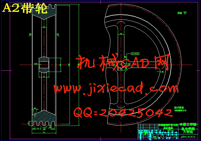
丝锥前稍专用铲背车床适用于直径范围为14~68mm,槽数为4或6的直槽丝锥前稍的铲背。该车床的进给传动系统的起始端为主轴,终端为凸轮,凸轮转动时带动刀架往复运动,对工件进行加工。本课题主要是从主传动系统与进给传动系统的运动设计、主运动部件与进给运动部件的结构设计和凸轮设计这三方面进行设计。
主传动系统与进给传动系统的运动设计有:确定极限转速、确定公比、确定转速级数、确定结构网和结构式、绘制转速图、确定齿轮齿数和拟定传动系统图。
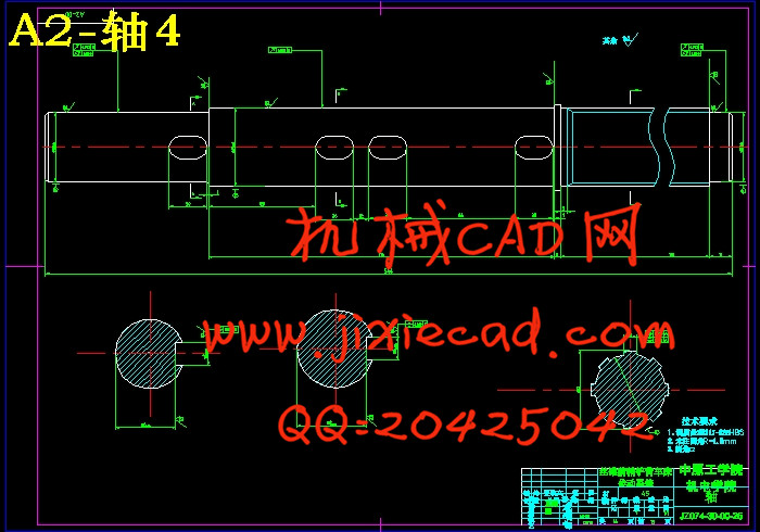
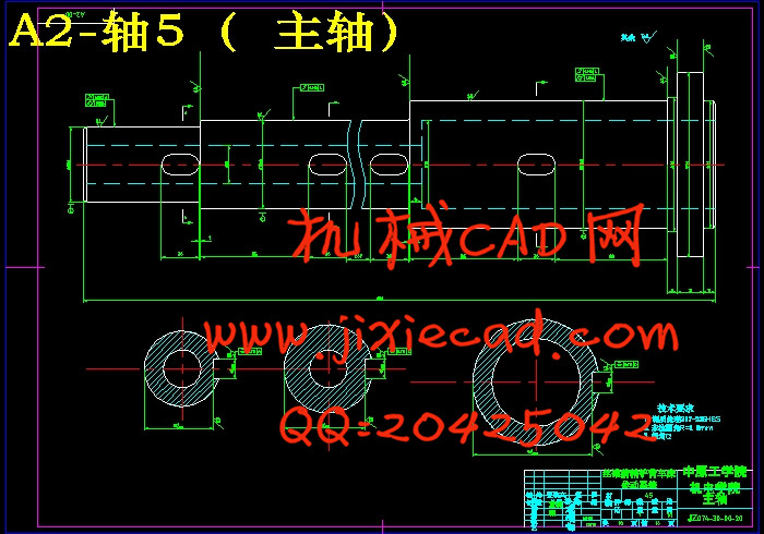
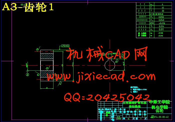
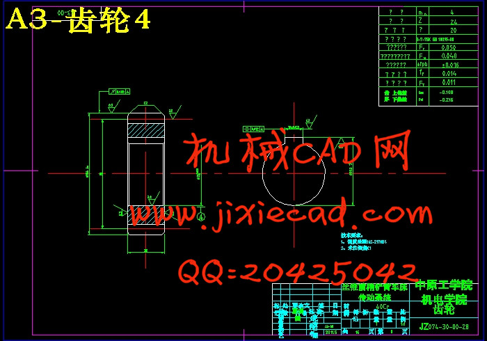
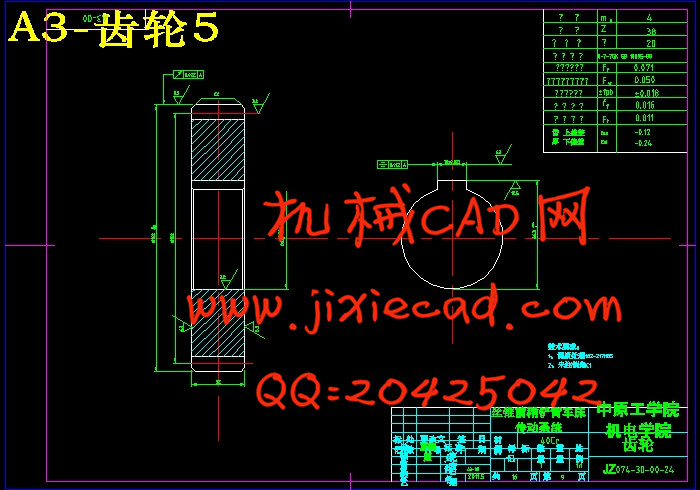
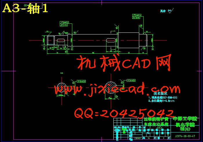
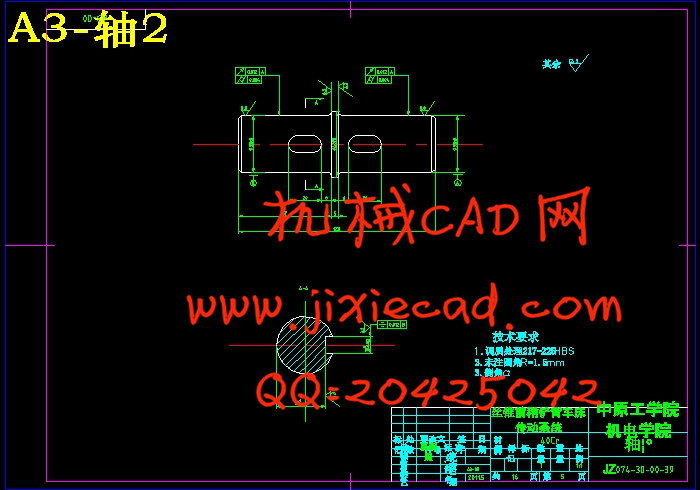
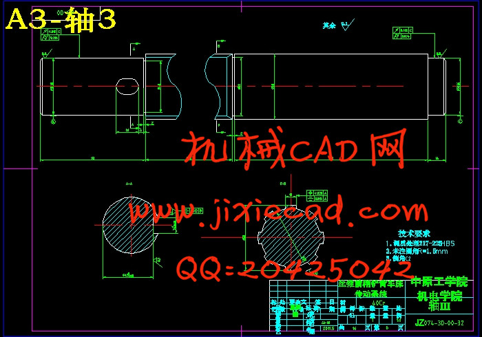
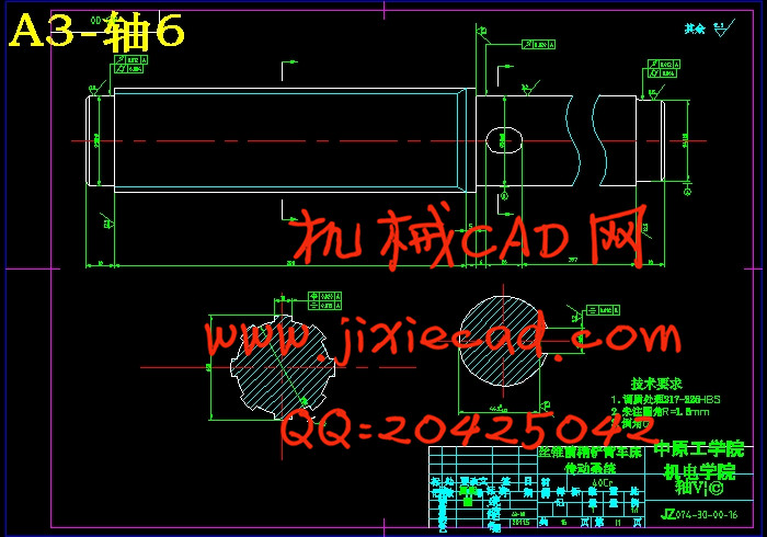
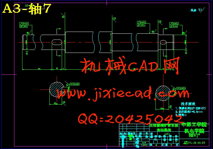
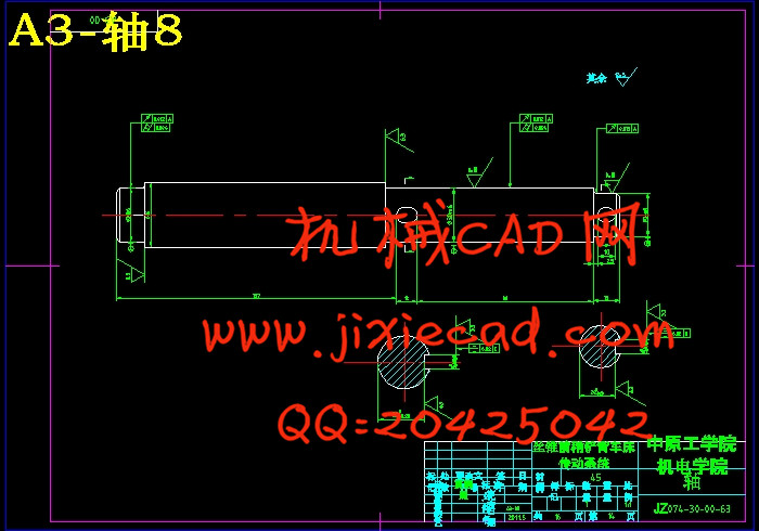
主运动部件与进给运动部件的结构设计有:带传动的设计、确定各种计算转速、确定齿轮模数、估算各轴直径和设计各轴、齿轮及部分主件。
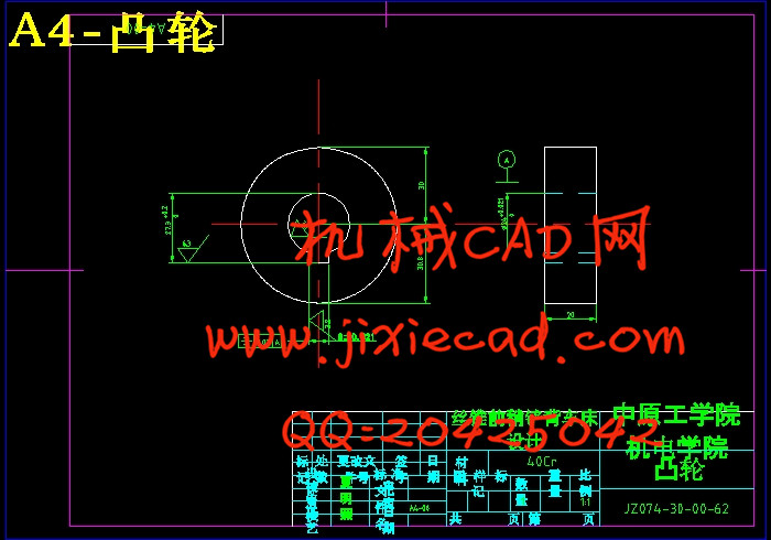
凸轮的设计有:根据加工要求确定从动件的运动规律、确定凸轮基本尺寸、确定凸轮轮廓。
关键词:铲背车床 传动系统 凸轮
Abstract
Tap front scraping special lathe can relieving grinding straight slot taps of diameter range is14 ~ 68 mm and slot number is 4 or 6. The initiator of the feed drive system of this lathe is the spindle,and the terminal is the cam. Cam driven tool holder when the reciprocating motion of the workpiece processing .The subject includes three main areas: the movement design of the main drive system and the feed drive system, the main moving parts and moving parts of the feed structure design and cam design.
Main transmission system and feed drive system design: determine the movement speed, and determine the speed, structure, and structured, rendering speed diagram, the pinion gear transmission system and the plan.
The moving parts of structure design: belt transmission design and calculation speed, determine the gear module,
Structural design of the main moving parts and feed moving parts: belt transmission design and calculation speed, determine the gear module, each shaft diameter and the design of main shaft parts, estimate the diameter of the shaft and design of the shaft, gear and some of the main pieces .
Cam design: According to the processing requirements to determine the movement of the follower, determine the basic size of cam,determine the cam profile.
Key words:Tap front scraping lathe transmission system cam
目 录
摘 要 1
引 言 3
第1章 绪论 4
1.1机床设计的主要意义 4
1.2主轴设计的重要性 4
1.3 主要设计内容 4
1.4 主要技术参数 4
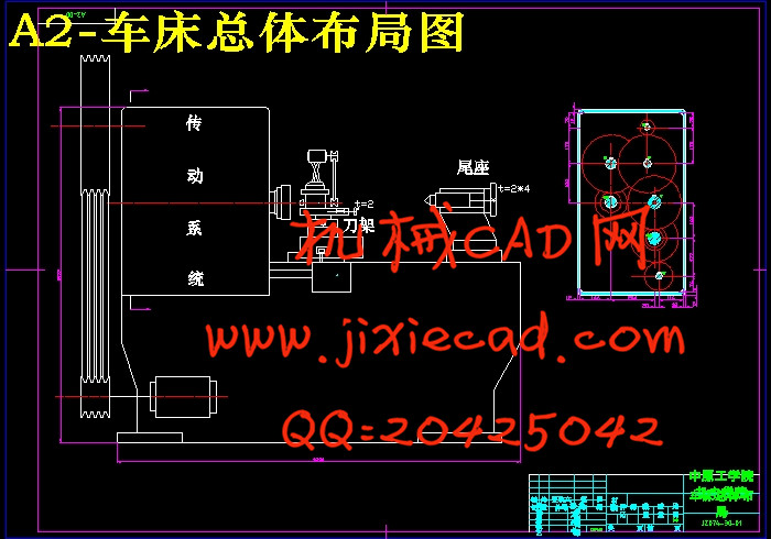
1.5 车床总体布局 4
第2章 车床主传动系统方案设计 6
2.1 主传动的组成及要求 6
2.2 主传动系统的传动方式 7
2.3 主传动的变速方式 7
第3章 主传动系统的运动设计 9
3.1 确定极限转速 9
3.2 确定公比 9
3.3 求出主轴转速级数 9
3.4 确定结构网和结构式 9
3.5 绘制转速图 10
3.6 齿轮齿数的确定 11
3.7 传动系统图的拟定 12
第4章 进给传动系统的运动设计 13
4.1 确定传动副数目 13
4.2 确定各齿轮齿数 13
4.3 确定主传动系统与进给传动系统传动系统图 14
第5章 主运动与进给运动主要部件结构设计 15
5.1 带传动设计 15
5.2 确定计算转速 17
5.3 各传动组齿轮模数的确定 19
5.4各轴直径的估算 22
5.5 轴的结构设计 24
5.6 轴的强度校核计算 24
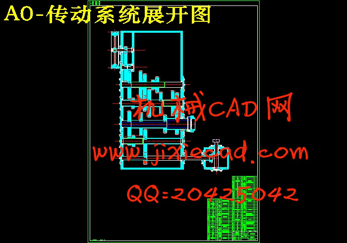
5.7 作出传动系统展开图 28
第6章 凸轮设计 30
6.1 凸轮机构的运动规律 30
6.2等速直线运动曲线凸轮轮廓曲线方程 31
6.3 凸轮设计过程 32
结 论 36
致 谢 37
参考文献 38


