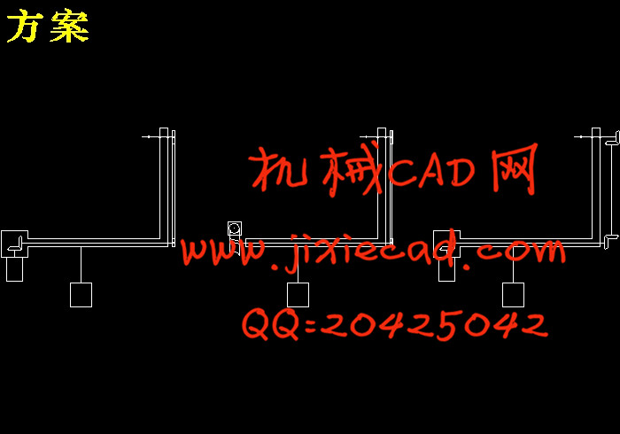
设计简介
中文摘要
七孔探针是一种能够同时获得流场中流动速度的大小、方向、总压和静压的气动测量装置,它主要依靠其头部七个孔道中气流压力的相对大小判断气流速度的大小与方向,被广泛应用于低速风洞实验各种大角度的流动测量。七孔探针测量流动角度范围大并且设备简单、对环境要求低、价格低廉用于流场的测量有着广阔的前景。 本文研究的是一种七孔探针三维自动测速系统的机械结构设计,该机械结构具有两个转动自由度和较高的传动精度。能够使探针实现相互垂直的回转运动。该系统由七孔探针,异步电动机,行星齿轮减速器,直锥齿轮,同步带传动系统组成。其特点是大广角,β角的范围从-65°到75°、高灵敏度、系统的测速范围从4m/s到50m/s、系统的旋转角度从0°到360°。整个测量过程全部由计算机自动控制,自动进行数据处理。关键词:七孔探针 风洞实验 自动标定
Abstract
Seven-hole probe is a way to get the size of the flow field flow velocity, direction, while the total pressure and static pressure pneumatic measuring device, which mainly depends on the size of the head of the seven channels in air pressure to determine the relative size of the flow velocity and direction,and it is widely used for testing a variety of wide-angle measurement of the flow in low-speed wind tunnel. Seven-hole probe measurements large flow angle range, simple equipment,low price and lowly requestment on the environment. It has broad prospects in measurement of the flow field. A 3D Velocity automatic measuring system using seven-hole probe is discussed in this paper. The mechanical structure with two rotational degrees of freedom, the transmission accuracy are higher. To probe the rotarymotion perpendicular to each other. The system developed by the author consists of a seven-hole probe, a stepping motor, a Planetary gear reducer, a straight bevel gears, a synchronous belt system.The advantages of this system with large space angle,β is from-65°to75°are highly sensitive. The velocity range of this system is from 4m/s to 50m/s. The rotation angle of this system is from 0°to360°. The process of measure ment is controlled by the computer. The experimental results show that the seven-hole probe tube automaticve locity measuring system is a very useful tool in study of aerodynamic characteristics in flow field.Key words: seven-hole probe,wind tunnel experiment,automatic calibration目 录
中文摘要
Abstract
第一章 绪论 1
1.1 风洞及七孔探针简介 1
1.2探针标定技术的发展状况 5
第二章 探针自动定位结构总体设计 7
2.1系统组成 7
2.2系统特性 7
2.3总体方案拟定 8
2.4主要设计参数及校核 11
2.5探针支架的具体设计 15
2.5.1 Y轴部分转动设计 16
2.5.2 X轴转动设计 16
2.5.3夹具部分设计 17
2.5.4底座设计 18
2.6材料选择 19
2.7同步带的参数设计及选择 19
2.7.1同步带的概述 19
2.7.2同步带的特点 20
2.7.3同步带传动的主要失效形式 21
2.7.4同步带传动的设计准则 23
2.7.5同步带分类 24
2.7.6同步带的主要参数 24
2.7.7同步带及带轮的选择 26
第三章 电机选择和芯轴设计 27
3.1伺服电机的选取 27
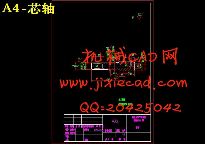
3.2芯轴结构设计 27
3.3芯轴强度校核 28
第四章 探针自动标定机构使用时注意事项 29
4.1 安全要求 29
4.2实施方法 29
结论
致谢
参考文献


