设计简介
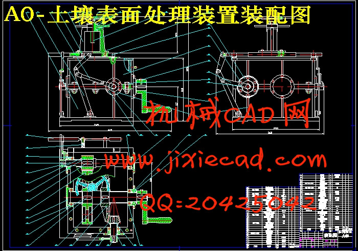
土壤表面整平装置
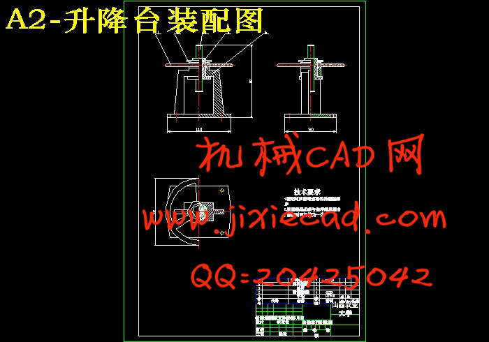
摘 要 本次设计的基于近红外光谱测试的土壤表面处理装置机构主要供实验室专用,其尺寸不宜过大,基于运动速度不是很大且较易控制,采用手动输入动力即可,其动力是通过不完全齿轮来传送的。本设计选用曲柄滑块机构来实现其在X和Y两方向上的往运动,但为了满足在两个方向上的独立运动,需用导杆结构。工作台设在导轨上面,为了能使其实现上下运动,在设计中选用螺旋升降机构。
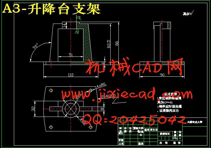
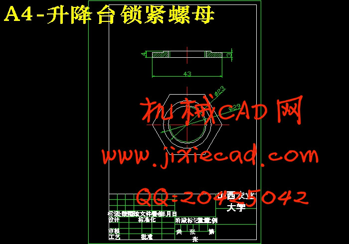
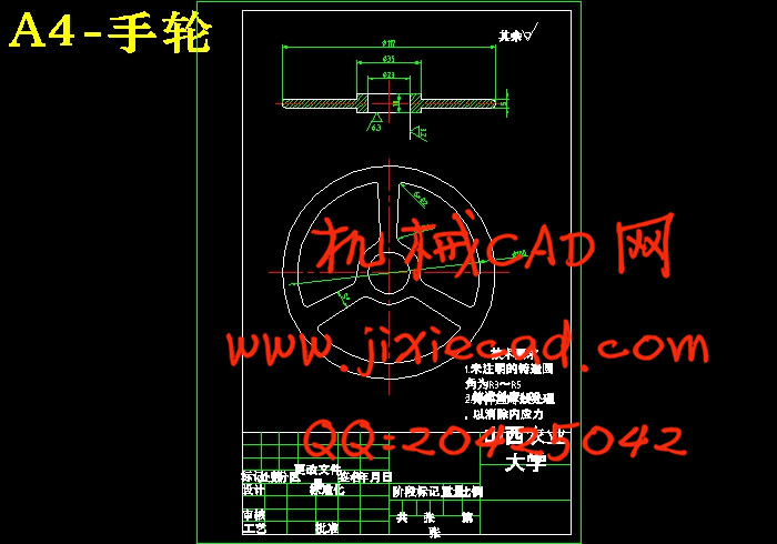
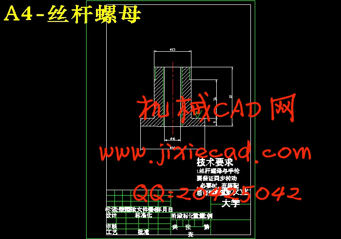
在设计过程中用Pro/E对螺旋升降机构进行三维实体建模,共有六个零件图和四个组装图。零件图主要有:底座支架、丝杠螺栓、紧固件螺母、手轮、丝杠、和底座紧固螺栓;组装图有:底座支架和丝杠螺栓的组装、底座支架丝杠螺栓和手轮的组装、底座支架丝杠螺栓手轮和螺母的组装、底座支架丝杠螺栓手轮螺母和丝杠的组装。另外,还有零件的分解及渲染。
关键词 土壤整平机 升降机 Pro/E 三维建模
Abstract
The design of the test based on near-infrared spectroscopy of soil surface treatment plant laboratories dedicated mainly for its size not be too big, based on the velocity and easier to control, you can manually input power, the power is not entirely through the transmission gear to. The design of slider-crank mechanism chosen to achieve its X and Y direction to the two campaigns, but in both directions in order to satisfy the independence movement, need to guide the structure. Table located in the guide above, in order to make it up and down movement, in the design of spiral movements in selected institutions.
During the design process using Pro / E on the spiral movements of three-dimensional solid modeling agencies, a total of six maps and four parts assembly. Fig main parts: the base frame, screw bolts, nut fasteners, hand wheels, screw and bolt fastening base; assembly plans are: the base of the brackets and screw bolt assembly, bolt and screw the base stent handwheel the assembly, the base bracket and screw hand wheel nut bolt assembly, the base bracket screw bolt and nut handwheel lead screw assembly. In addition, there are parts of the decomposition and rendering.
Keywords Soil leveling machine Lift Pro/E Three-dimensional modeling
目录
1 绪论 1
1.1 设计的目的 1
1.2 设计的意义 1
2 技术任务书 (JR) 1
2.1所要设计的主要机构 1
2.2所要解决的问题及解决问题的方法 2
2.2.1解决的问题 2
2.2.2 解决方法 2
2.3装置的总体设计 3
3 设计计算说明书 (SS) 4
4 螺旋升降机构的设计 4
4.1 螺旋传动机构的选择 4
4.2 滑动螺旋的结构和材料 4
4.2.1 滑动螺旋结构 4
4.2.2 材料 4
4.3升降机构的设计 5
4.3.1底座的设计 5
4.3.2 手轮的设计 5
4.3.3 紧固件螺母的选用 5
4.3.4 丝杆的尺寸参数 6
5 曲柄滑块机构的设计 7
5.1 连杆机构及其传动特点 7
5.1.1 连杆机构的传动特点 7
5.1.2 连杆机构的型式及设计原理 8
5.2 曲柄滑块机构的选用及连杆设计 9
5.2.1 曲柄滑块机构的选用 9
5.2.2 连杆的设计计算 10
6.Pro/E的发展历程及其应用领域 11
6.1 Pro/E的发展历程 11
6.2 Pro/E的应用领域 12
6.2.1创建二维草图 12
6.2.2三维实体建模 12
6.2.3零件的渲染 13
6.2.4装配体的分解 13
6.2.5 Pro/E的运动仿真 13
7螺旋升降机构的三维步骤 14
7.1底座支架的绘制 14
7.1.1底座的绘制 14
7.1.2加肋板 16
7.1.3底板两端圆的绘制 17
7.1.4底板孔的绘制 19
7.1.5支架顶圆及圆台的绘制 20
7.2手轮的绘制 23
7.3锁紧螺母的绘制 25
7.4丝杠螺栓的绘制 29
7.5丝杠的绘制 32
7.6螺栓的绘制 33
8零件的组装 35
8.1底座支架与丝杠螺栓的组装 35
8.2手轮的组装 36
8.3螺母的组装 37
8.4丝杠的组装 37
9.零件的渲染 38
10.创建装配分解图 39
11.使用说明书 (SM) 40
12.标准化审查报告 (BS) 40
12.1 产品图样的审查 40
12.2 产品技术文件的审查 41
12.3 标准件的使用情况 41
12.4 审查结论 41
结论 42
参考文献 44
致谢 45


