设计简介
摘要
蛙式打夯机的工作原理是通过带传动,夯机体在偏心块离心力的作用下做上下冲击振动,从而压实物料。同时,离心力的作用也使得机体自行前移。
本文完成了蛙式打夯机的设计,具体包括对偏心块、轴、带轮、夯头架的结构设计,并对机器上主要构件(如轴、各主要连接螺栓)进行了强度校核计算。本文设计的蛙式打夯机结构小巧,装拆方便,在进行小面积薄铺层的平整和初步压实加工的过程中,能发挥较大的作用。
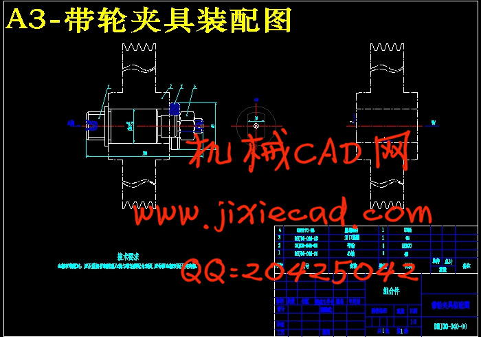
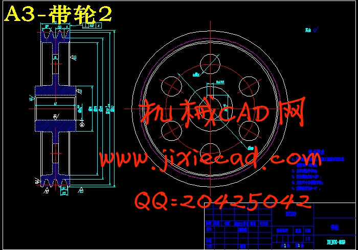
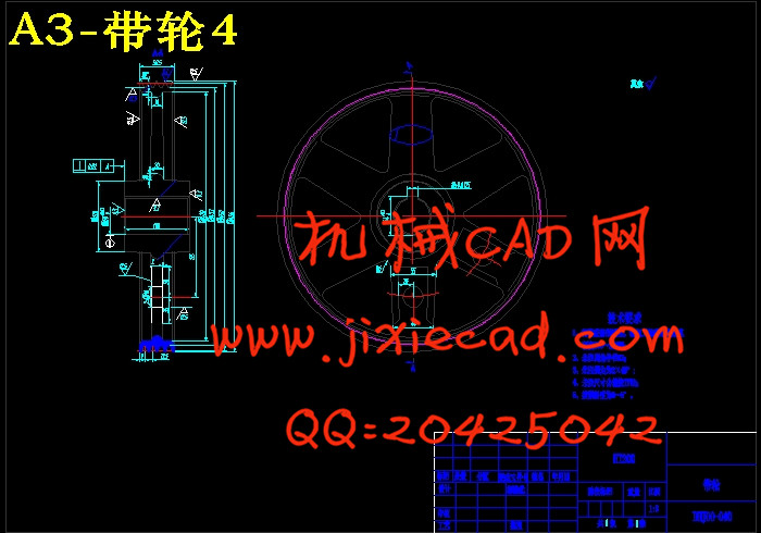
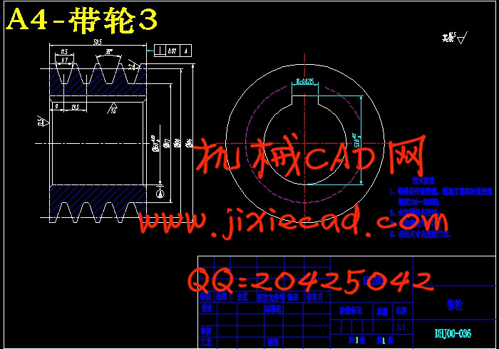
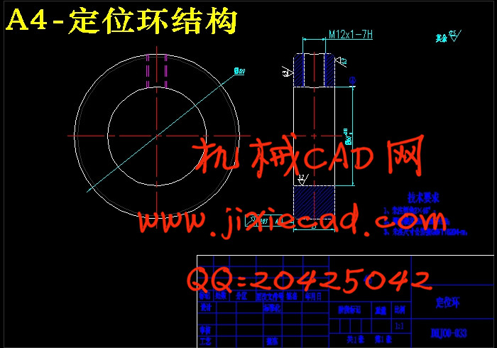
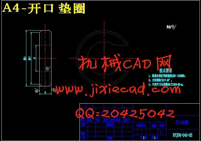
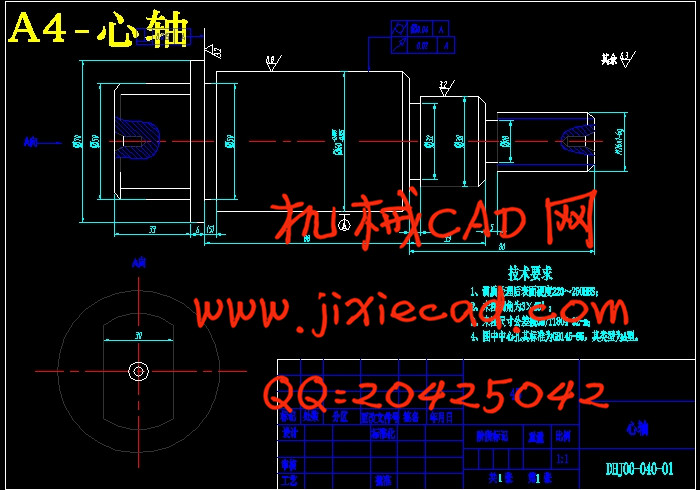
最终完成了蛙式打夯机总装配图和主要零部件的零件图的设计,并完成了输出大带轮和心轴的加工工艺及工装的设计,绘制了专用夹具图。
关键词:蛙式打夯机,离心力,结构设计。
ABSTRACT
蛙式打夯机的工作原理是通过带传动,夯机体在偏心块离心力的作用下做上下冲击振动,从而压实物料。同时,离心力的作用也使得机体自行前移。
本文完成了蛙式打夯机的设计,具体包括对偏心块、轴、带轮、夯头架的结构设计,并对机器上主要构件(如轴、各主要连接螺栓)进行了强度校核计算。本文设计的蛙式打夯机结构小巧,装拆方便,在进行小面积薄铺层的平整和初步压实加工的过程中,能发挥较大的作用。
最终完成了蛙式打夯机总装配图和主要零部件的零件图的设计,并完成了输出大带轮和心轴的加工工艺及工装的设计,绘制了专用夹具图。
关键词:蛙式打夯机,离心力,结构设计。
ABSTRACT
The working principle of breaststroke ramming machine (BRM) is that through the belt transmission, the body of BRM vibrates up and down functioned by the eccentric centrifugal force to compact material. Simultaneously the eccentric centrifugal force is able to make the body of BRM move forward voluntarily.
In the paper, the design tasks of the BRM include the structure design of eccentric, axis, belt wheel and ramming head. Strength of the major components such as shaft, connecting bolts is calibrated in the thesis. The BRM designed in the paper has features of compact structure and convenience for the assembling and dismantling, so it can play an important role to smooth the small area thin layer and to do the preliminary compaction process.
Finally, an assembling drawing of the BRM and the major part drawings are completed and the technological process of large output pulley and its fixture are designed, too
Keywords: Ramming Breaststroke Machine, Centrifugal Force, Structure Design.
目 录
中文摘要 Ⅰ
英文摘要 Ⅱ
第1章 绪论 1
1.1 蛙式打夯机的发展现状 1
1.2 本设计的设计目的 1
1.3 本设计中的蛙式打夯机结构简图 2
第二章 电机功率的确定 3
2.1 确定偏心块质量和工作功率 3
2.1.1 确定偏心块质量 3
2.1.2 确定电机所需功率 4
第三章 确定V带型号和带轮直径 5
3.1 确定V带选用类型 5
3.1.1 V带尺寸的确定 5
3.2 带疲劳强度及寿命校核 5
3.2.1 带的工作应力计算 5
3.2.2 带的寿命计算 7
3.3 计算一级带轮直径及所受载荷 7
3.3.1 计算带轮D
3.3.2 求轴上载荷 8
3.3.3 带轮结构 8
3.4 计算二级带轮直径及轴上载荷 10
3.4.1 计算带轮D
3.4.2 求轴上载荷 10
3.4.3 带轮结构 11
第四章 轴的设计 13
4.1 带轮4上轴的设计 13
4.1.1 初步确定轴的尺寸 13
4.1.2 带轮4上轴的整体设计 13
4.1.3 轴的受力校核 14
4.2 带轮3上轴的设计 16
4.2.1 初步确定轴的尺寸 16
4.2.2 轴的受力校核 17
第五章 键的选择与校核 20
5.1 带轮1上键的选择与校核 20
5.1.1 键的选择 20
5.1.2 键的校核 20
5.2 带轮2上键的选择与校核 21
5.2.1 键的选择 21
5.2.2 键的校核 21
5.3 带轮3上键的选择与校核 22
5.3.1 键的选择 22
5.3.2 键的校核 22
5.4 带轮4上键的选择与校核 23
5.4.1 键的选择 23
5.4.2 键的校核 23
第六章 紧固螺栓的强度校核 24
6.1 轮4上轴承座与夯头连接螺栓的强度校核 24
6.2 偏心块与轮4连接螺栓的强度校核 24
6.3 离心力大小对整机设计的检验 25
6.3.1 检验整机前移时离心力的大小 25
6.3.2 检验夯头抬升及底板部分抬升时离心力的大小 25
6.4 两轴间连架杆的压杆稳定性校核 25
6.5 轴1上轴承使用寿命校核 26-1
第七章 带轮加工工艺设计 27
7.1 零件的分析 27
7.1.1 零件的作用 27
7.1.2 零件的工艺分析 27
7.2 工艺规程的设计 27
7.2.1 基准的选择 27
7.2.2 制定工艺路线 27
7.2.3 机械加工余量、工序尺寸及毛坯尺寸的确定 28
7.3 确定切削用量及基本工时 28
7.4 专用夹具的设计 36
第8章 设计总结 39
参考文献 41
致谢 42


