设计简介
摘要:
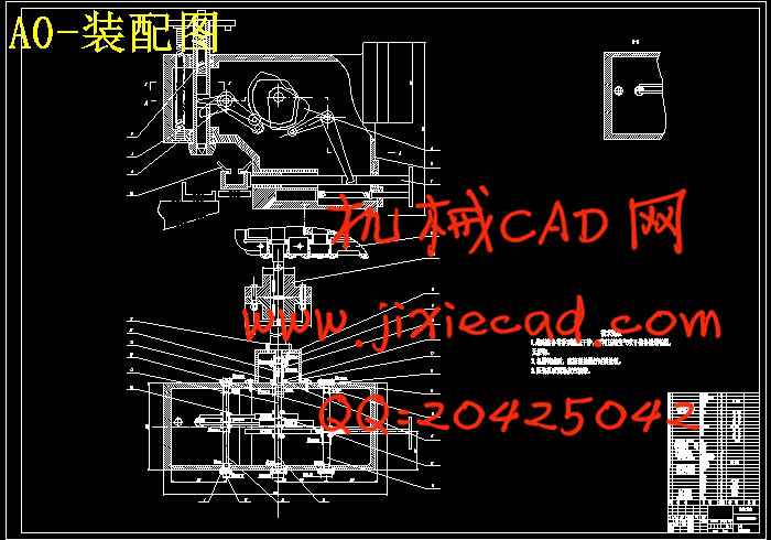
本课题旨在解决仪表生产中的锥形薄片压入的工序自动化问题,既要保证压入的位置,同时必须保证锥形薄片在同一位置产生精度相同的变形。完成了压装机构的运动分析、工序设计、主要依靠三个凸轮的运动实现。第一个凸轮通过其摆动从动件控制夹紧轴的水平移动,第二个与第三个凸轮通过其摆动从动件分别控制内轴与外轴垂直移动,使其定位和冲压。
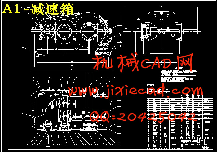
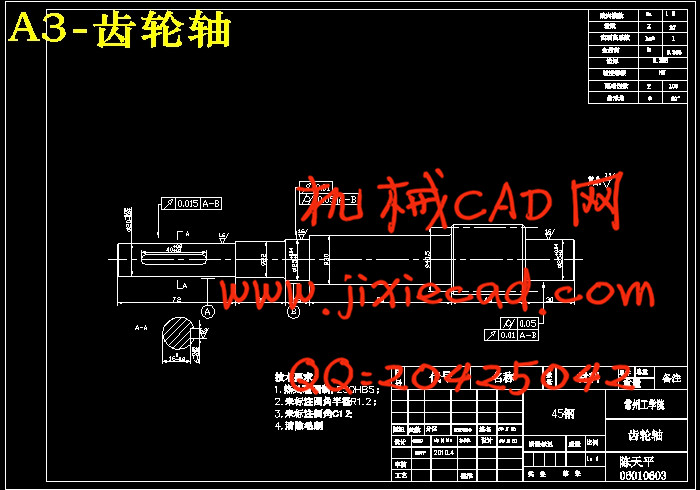
进行了结构设计及关键零部件设计。其中有仪表壳的尺寸,装配夹具形状及尺寸,从动件的位移线图的设计,凸轮的设计,其中为了压装机的运作设计了减速箱,减速箱里包括电机的选择,V带的设计和齿轮的设计,最后选择了连接压装机和减速箱的联轴器。
关键词: 凸轮,弹簧,齿轮,齿轮轴,电机。
Abstract:
The subject aimets at solving the process automation problem of tapered chip in production of instrument. Not only ensure the position of pressure, but also must ensure tapered chip in the same location have the deformation. Completed pressing institutions kinematic analysis,process desin,mainly rely on the movement o achieve the three cam, the first cam though the swinging clamping axis control axis level migration, the second and the third cam through swinging clamping axis to distinction control inner axis and outer axis vertical migration to fix position and hurtle press.
Carrying on the structure design and the key partses design. Which have size of instrument shell, assemble fixture shape and size, driven document moves the line diagram, the design of cam, among them for the sake of operation to designing the reducer casing. Reducer casing include the electrical motor choice, the V take design and the wheel gear design, finally chose shaft couping to connect pressure institutions and reducer casing .
Key words: CAM, spring, gear, same dethegear motor shaft.
目录
摘要
第一章、关于课题..........................................................1
1.1序言...............................................................1
1.2 课题来源及现状....................................................1
1.3 设计要求..........................................................1
第二章、压装机的设计.......................................................2
2.1 仪表壳............................................................2
2.2 装配夹具..........................................................2
2.3 压头..............................................................3
2.4凸轮机构的设计.....................................................3
2.4.1 凸轮机构的组成. ................................................3
2.4.2 凸轮机构的类型..................................................3
2.4.3 从动件常用运动规律特征比较及适用场合.............................. 4
2.4.4 运动规律的组合................................................. 4
2.4.5 从动件运动规律的选择............................................ 5
2.4.6凸轮廓线的设计 ................................................. 5
2.4.7凸轮轮廓的加工方法 .............................................10
2.4.8 凸轮机构的压力角...............................................10
2.5轴的设计..........................................................10
第三章、减速箱的设计.....................................................13
3.1 减速箱的示意图...................................................13
3.2 各主要部件的选择.................................................13
3.3 电动机的选择.....................................................13
3.4 分配传动比.......................................................14
3.5 V带传动的设计....................................................14
3.6 设计高速轴齿轮...................................................16
3.7 设计低速级齿轮...................................................20
3.8 齿轮润滑方式的选择...............................................20
3.9 密封方式的选择...................................................20
第四章、联轴器的设计选择..................................................21
第五章、总结.............................................................23
第六章、致谢.............................................................24
参考文献.................................................................25


