设计简介
摘 要
数控机床在机械加工行业中的应用越来越广泛。数控机床的发展,一方面是全功能、高性能;另一方面是简单实用的经济型数控机床,具有自动加工的基本功能,操作维修方便。经济型数控系统通常用的是开环步进控制系统,功率步进电机为驱动元件,结构简单,系统的定位精度较高。普通车床刀架的纵向和横向进给运动是由主轴回转运动经挂轮传递而来,通过进给箱变速后,由光杆或丝杆带动纵溜板、横溜板的移动。进给参数要靠手工预先调整好,改变参数时要停车进行操作,刀架的纵向进给运动和横向进给运动不能联动,切削次序也由人工控制。
对普通车床进行数控化改造,主要是将纵向和横向进给系统改造成为微机控制的,能独立运动的进给系统,刀架改造为能自动换刀的回转刀架。这样,利用数控装置,车床就可以按预先输入的加工指令进行切削加工。由于切削过程中切削参数,切削次序和刀具都会按程序自动运行,调节和更换,再加上纵向和横向联动的功能,数控改装后的车床就可以加工出各种形状复查的回转零件,并能实现多工序自动加工车削,从而提高了生产效率和加工精度,也能适合小批量多品种复查零件的加工。
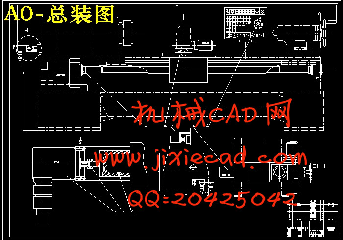
C6132车床改造属于经济型数控车床的改造,主要针对进给系统进行数控化改造,利用数控系统对纵、横向进给系统进行开环控制,驱动元件采用步进电动机,车床通过步进电动机带动滚珠丝杠转动。
关键词:微机控制;伺服系统;回转刀架;自动车削
ABSTRACT
The numerical control engine bed is more and more widespread in machine-finishing profession application. Numerical control engine bed development, on the one hand is the entire function, the high performance; On the other hand is the simple practical economy numerical control engine bed, has the automatic processing the basic function, the operation service is convenient. The economy numerical control system passes commonly used is the split-ring step-by-steps the control system, the power step-by-steps the electrical machinery for to actuate the part, does not have the examination feedback organization, the system pointing accuracy is high. Knife rest vertical to enter, give sport and horizontal to stock for sport to can be linked, cut order by artificial control even.Carry on the numerical control transformation to the ordinary lathe. Mainly vertical and horizontal enter give system transform into by what computer control.The knife rest is transformed into the gyration knife rest that can be changed one hundred sheets automatically. Introduces the engine bed the microcomputer numerical control system the transformation to be possible to enhance the engine bed the operational performance,Reduces the production cost,Obtains the high economic efficiency with the few funds investmentTake the C6132 lathe numerical control transformation as the example,In line with are as far as possible few to the lathe modification,Control section anti-jamming,Transformation cost low principle,Carries on the numerical control transformation to the lathe.
Lathe for the NC transformation is mainly vertical and horizontal feed system into a computer-controlled, The independence movement can feed system can transform Tool Automatic Tool Change of Rotary Tool. Thus, the use of NC devices, lathe can be imported at a pre-processing machining instructions. As the cutting process of cutting parameters, priorities and cutting tool will automatically by operation, regulation and replacement, coupled with the vertical and horizontal linkage functions, CNC lathe after the conversion can be processed into various shapes review the rotating parts, and multiple processes can be automatically processed turning, thus enhancing the efficiency of production and processing accuracy, also suitable for small batch multiple types of review parts of the processing.
C6132 lathe belongs to economic numerical control lathes transformation of transformation, mainly in the numerical control system by using nc system transformation, of transverse and longitudinal feeding system, open loop control by stepping motor driver components, lathe, through the stepper motor driving ball screw rotation.
Key words:the computer controls; servo system; turn the knife rest round; automatic turning
目 录
1 前 言 1
2 设计方案 3
2.1 总体方案的确定 3
2.1.1 系统的运动方式与伺服系统的选择 3
2.1.2 计算机系统 3
2.1.3 机械传动方式 3
2.2 系统运动方式的确定 3
2.3 伺服系统的选择 3
2.4 执行机构传动方式的确定 4
2.5 计算机的选择 4
2.6 总体方案框图绘制 4
3 横向进给伺服系统机械部分计算与校核 5
3.1 计算切削力 5
3.2 滚珠丝杆螺母副的设计、计算、选型 5
3.2.1 计算进给牵引力 5
3.2.2 计算最大动负载C 6
3.2.3 滚珠丝杆螺母副的选型 6
3.2.4 传动效率计算 7
3.2.5 刚度验算 7
3.2.6 稳定性校核 8
3.2.7 横向滚珠丝杆副的几何参数 9
3.3 齿轮传动比计算 10
3.4 横向步进电机计算和选型 11
3.4.1 初选步进电机 11
3.4.2 校核步进电机转矩 12
3.5 横向进给伺服系统机械部分结构设计 17
3.5.1 横向进给伺服系统总图设计 17
3.5.2 进给伺服系统的装配图 18
4 纵向进给伺服系统机械部分计算与校核 20
4.1 计算切削 20
4.2 滚珠丝杆螺母副的计算和造型 20
4.2.1 计算进给牵引力 20
4.2.2计算最大动负载C 21
4.2.3 滚珠丝杆螺母副的选型 21
4.2.4 传功效率计算: 21
4.2.5 刚度验算 22
4.2.6 稳定性校核 23
4.2.7纵向滚珠丝杆副几何参数 23
4.3 齿轮传动比计算 24
4.3.1 进给齿轮箱传比计算 24
4.4 步进进电机的计算和选型 25
4.4.1 初选步进电机 25
4.4.2 校核步进电机转矩 27
4.5 纵向进给伺服系统机械部分结构设计 31
4.5.1 纵向进给伺服系统总图设计 32
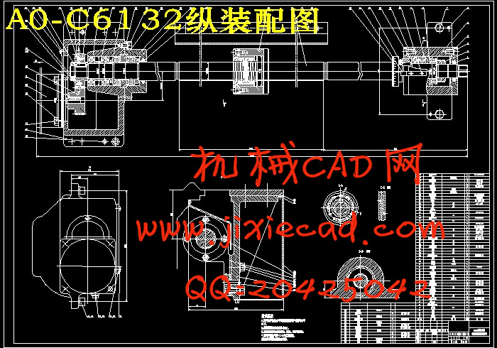
4.5.2进给伺服系统的装配图 32
5 微机数控系统硬件电路的设计 34
5.1硬件电路一般要求 34
5.2控制系统的组成及功能 34
5.2.1 CPU、存储器、I/O接口电路扩展 34
5.2.2控制系统的功能 36
5.3步进电机控制电路 36
5.3.1步进电机开环驱动原理 36
5.3.2脉冲分配 37
5.3.3驱动电路 37
5.3.4其他辅助电路 38
6 微机控制系统的软件设计 39
6.1 监控程序 39
6.2 直线圆弧插补程序设计 39
6.3升降速处理软件 41
6. 4步进电机的软件控制及转程序设计 43
7 机床的加工程序编制 46
致 谢 49
参考文献 50
附 录 51


