设计简介
摘 要
近年来机器人的研究和应用已经不仅仅局限于军用领域。许多应用于军用机器人上的成功技术已经在民用机器人中得到了一定的应用。在工业机器人的基础上,运用了传感器技术和单片机智能控制技术,设计出了一种能自动运送货物的职能巡线机器人。论文首先对智能巡线机器人总体设计方案进行叙述,阐述其各要素的工作原理,然后就整个智能巡线机器人系统划分为五个模块,分章节对各个模块设计制作进行阐述。
机器人机械结构部分,通过分析常用的车轮驱动配置方式,择优选择了前排安装两个万向轮、后排安装两个独立驱动轮的设计方案,充分考虑到了巡线的简易性和稳定性。
机器人传感器接口与驱动电路部分,详细阐述了光电传感器检测信号原理,叙述了设计所采用的光电传感器接口电路详细设计方案,分析了传感器采用该种布局方案的原因。针对机器人的机械特性和速度要求,选用了L298N驱动芯片驱动电机,分析了它的优缺点和可行性。
机器人主控系统硬件部分阐述了主控芯片选型,主控电路设计方案,以及相应的接口说明。软件部分在MSP430平台上实现了快速、稳定、准确的巡线方法。
关键词: 机器人;巡线;光电检测;PWM驱动。
Abstract
In recent years, research and design of robot has not been limited just in military field. Many technologies, which had been used in the military field cuccessfully, have been used in the field of civilian robot. Based on the industrial robot, and by applying sensor interface control and SCM intelligent control, this project has designed one kind of biranpower line walking robot that is able to carry the goods by itself.In this thesis, the overall design of autonomous line-tracking robot and principle of each essential element have been described. The robot system has been divided into five parts as fellow.
The autonomous line-tracking arithmetic is the key of this project research. The relative position relationship between the robot and the leading line is divided into seven typical states; the adjustment strategy has been described respectively. An implementation principle to enable centerline approaching the leading-line gradually has been described by adjusting continuously chassis posture.
In mechanical structure part, by analyzing the normal wheel drive configurations, it has been choiced that two universal wheels are installed in the front and two independent driving wheels are installed in the rear, which takes fully into account the simplicity and stability of the line-tracking.
In sensor interface and drive circuit part, a detail explanation of photoelectric sensor and interface circuit has been discussed carefully. To adapt the robot mechanical properties and speed requirement, two motor driving circuits based on different principles have been designed and their advantages and feasibility analyied.
In robot control system part, hardware and software have been discussed such as CPU choosing, control circuit designing, and hardware interface assigning, etc. Based on the MSP430, the speed difference from left and right wheel created by the Pulse-Width Modulation adjusts the position of the robot and leading line, which carries out the autonomous runs along with the leading line quickly, stably and accurately.
Keywords: Robot; Line-tracking; Photoelectric Sensor; PWM.
目 录
摘要 1
Abstract 2
前言 3
第1章 绪论 1
1.1 机电一体化技术简介 1
1. 2智能巡线机器人的概况 2
1. 3 课题的主要内容 2
第2章 自动巡线机器人总体方案设计 4
2.1 机器人要素分析 4
2.2 机器人总体分析 5
2.2.1 场地分析 5
2.2.2 机械结构分析 5
2.2.2控制系统框架设计 5
2.2.4运动姿态分析 5
第3章 机械结构设计 7
3.1 移动机器人的车轮驱动配置 7
3.1.1 机器人常用车轮驱动配置介绍 7
3.1.2 本系统所采用的车轮驱动方式配置 10
3.2 机器人机械尺寸设计 11
第4章 传感器接口电路设计 13
4.1 机器人对巡线传感器的要求 13
4.2 超声波传感器 13
4.2.1超声波传感器的原理 13
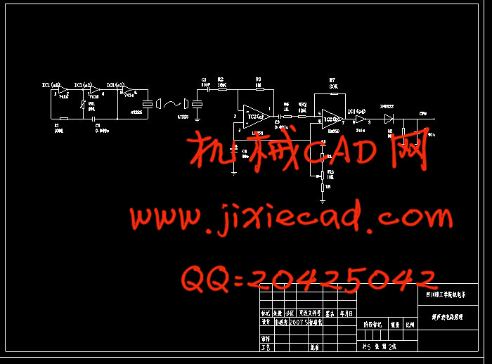
4.2.2 超声波的发射与接受电路 15
4.3 红外光电反射式传感器 15
4.3.1 红外光电反射式传感器原理 16
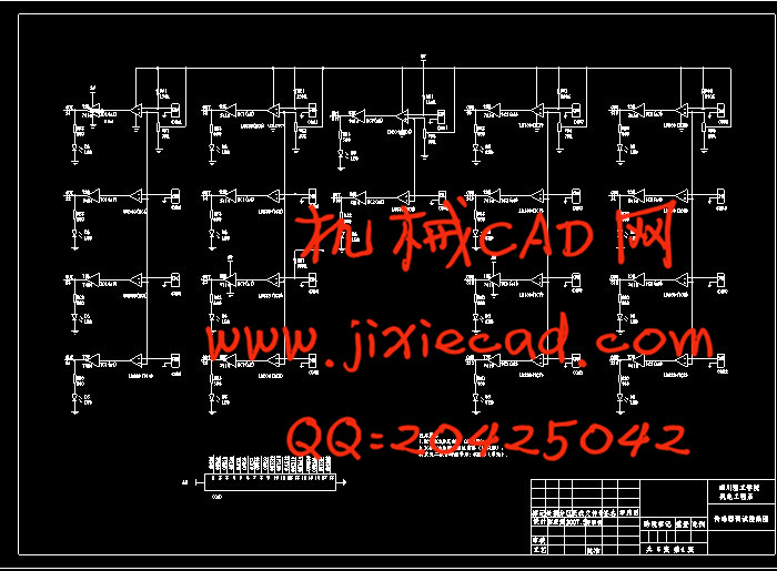
4.3.2 基于反射光强度测量的红外光电反射式传感器电路 17
4.4 红外光电反射式传感器布局 19
第5章 电机驱动电路设计 21
5.1 驱动电机的选用 21
5.1.1电机减速器的选择 22
5.1.2 所选电机性能校核 23
5.2 直流电机的转动控制 24
5.3 直流电机的速度控制 26
5.4基于L298的驱动电路 28
第6章 智能巡线机器人之态调整方法 31
6.1 总体分析 31
6.2 姿态分析 32
第7章 主控系统的设计 36
7.1 主控制芯片的选型 36
7.1.1 MSP430系列与89C51系列单片机 36
7.1.2 选用的MSP430F449的原因 38
7.1.3 MSP430F449的引脚 39
7.2 主控单元电路设计 39
7.3 MSP430实现巡线算法 43
7. 4巡线改进方法的实现 46
7. 5转弯分析 51
总结与展望 56
致谢 57
参考文献 58
附件一:程序 60
附件二:元件 76


