设计简介
摘要
汽车制动系的功用是使汽车以适当的减速度降速行驶直至停车;在下坡行驶时,使汽车保持适当的稳定车速;使汽车可靠地停在原地或坡道上。汽车的制动性是汽车主动安全性研究的重点内容之一。随着汽车行驶车速的不断提高,对汽车制动性能的要求也越来越高。汽车的制动系统除了实现良好的制动性能外,还要尽可能地减小驾驶员的工作强度。因此,动力制动系统在汽车上得到了广泛的应用。
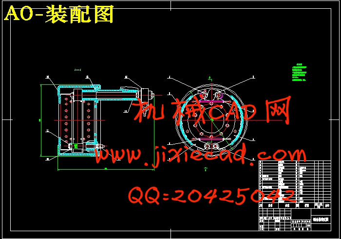
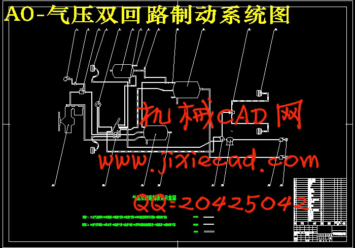
气压动力制动是最常见的动力制动系统,多用于中重型汽车。气压制动系统是发展最早的一种动力制动系统。其供能装置和传动装置全部是气压式的。其控制装置大多数是由制动踏板机构和制动阀等气压控制原件组成,也有的在踏板机构和制动阀之间还串联有液压式操纵传动装置。本文以一种重型货车为研究对象,通过理论分析和计算对其气压制动系统结构进行设计。
关键词:气压制动;制动性;重型货车;传动装置;
ABSTRACT
Automobile brake system function is to reduce the speed of cars to slow down and drive right up to parking,When traveling downhill, so that the stability of vehicle speed to maintain proper To make reliable cars parked in the ramp or in situ.汽车制动系的功用是使汽车以适当的减速度降速行驶直至停车;在下坡行驶时,使汽车保持适当的稳定车速;使汽车可靠地停在原地或坡道上。汽车的制动性是汽车主动安全性研究的重点内容之一。随着汽车行驶车速的不断提高,对汽车制动性能的要求也越来越高。汽车的制动系统除了实现良好的制动性能外,还要尽可能地减小驾驶员的工作强度。因此,动力制动系统在汽车上得到了广泛的应用。
气压动力制动是最常见的动力制动系统,多用于中重型汽车。气压制动系统是发展最早的一种动力制动系统。其供能装置和传动装置全部是气压式的。其控制装置大多数是由制动踏板机构和制动阀等气压控制原件组成,也有的在踏板机构和制动阀之间还串联有液压式操纵传动装置。本文以一种重型货车为研究对象,通过理论分析和计算对其气压制动系统结构进行设计。
关键词:气压制动;制动性;重型货车;传动装置;
ABSTRACT
The brake performance iS one of the most important safe performances for the automobile.With the increase of running speed of the vehicle;the requirements to the brake performance are getting more and more strict.Besides the good brake performance,the brake system of the automobile is required to reduce the pedal force of the driver.Therefore,the power servo brake system has made a great development in the automobile.
The barometric brake system is the most familiar power servo brake system.The barometric brake system is the first development of a dynamic braking system. Its energy supply all equipment and gear-type pressure Most of the control device is a brake pedal and the brake and other institutions formed the original, Also some in the brake pedal between institutions and also in series with hydraulic control gear. In this paper, the application of a kind of heavy goods vehicles, Through theoretical analysis and calculation of the structure of its air brake system design.
Key words;barometric brake syste;rake performance;heavy-duty truck;
Drive Equipment;
1绪论 1
1.1制动系的作用 1
1.2气压制动系的研究现状 2
2制动系的总体设计 3
2.1制动系统设计要求 3
2.2制动系参数的选择 4
2.3汽车总质量 4
2.4制动力与制动力分配系数 4
2.5制动器最大制动力矩 9
3制动器的设计与计算 12
3.1鼓式制动器的主要参数 13
3.1.1制动鼓内径 13
3.1.2摩擦衬片宽度b及包角
3.1.3摩擦衬片起始角
3.1.4制动蹄支撑点位置坐标a和c 15
3.1.5制动器中心到张开力F0作用线的距离e 15
3.1.6摩擦衬片的型号及摩擦系数
3.2鼓式制动器的计算 15
3.2.1计算有一个自由度的紧蹄摩擦片的径向变形规律 15
3.2.2 计算蹄片上的制动力矩 16
3.2.3检查制动蹄有无自锁 18
3.3 衬片磨损特性的计算 19
3.3.1比能量耗散率(单位功负荷、能量负荷) 19
3.3.2 衬片单位摩擦面积的制动器摩擦力f0 (比摩擦力) 20
3.3.3驻车制动计算 21
3.4制动鼓主要零部件的结构设计 21
3.4.1 制动鼓 21
3.4.2 制动蹄 22
3.4.3 制动底板 23
3.4.4 凸轮式张开机构 23
3.4.5 摩擦材料 23
3.4.6 支承 24
4气压制动驱动机构的设计计算 25
4.1制动气室 26
4.2贮气罐 28
4.3空气压缩机 30
5技术经济性分析 31
6总结 33
致谢 34
参考文献 35


