设计简介
自动锯床液压系统设计
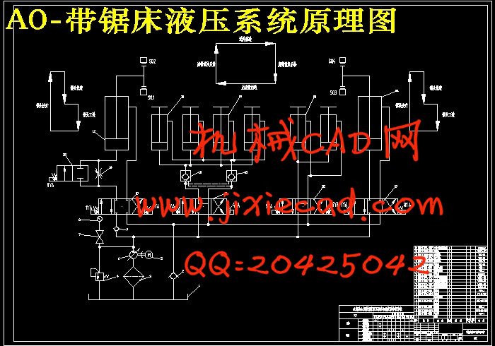
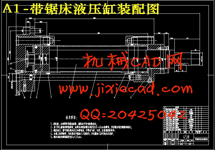
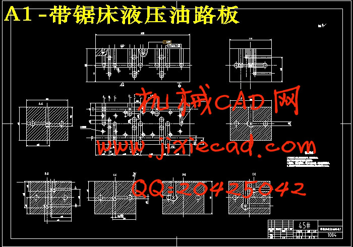
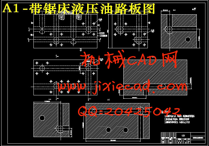
摘 要:首先明确全自动金属锯床对液压系统的要求,然后通过给定的技术参数表里的液压系统设计参数,确定液压执行元件的载荷力、系统工作压力以及液压缸的主要结构尺寸,制定系统方案,拟定液压系统图,然后进行液压元件的选择,最后对系统性能进行验算。在具体的结构设计中,主要是针对系统中涉及到的阀类元件的设计,油路板的设计等。
关键词:全自动金属锯床;液压系统;液压元件;液压系统图
The Design of Hydraulic Pressure System For The Automatic Sawing Machine
Abstract: First, clear about the request of the Automatic metal band sawing machinefor hydraulic system, and then through the given technical parameters and design parameters of the hydraulic system, to determine the hydraulic actuator loading system working pressure of hydraulic cylinder, and the main structure dimensions, make systematic plan, develop hydraulic system diagram, and then the choice of hydraulic components, final,conduct system performance calculation. In the specific design of the structure, is mainly directed against the system relates to the valve element design, circuit board design and so on.
Key words:Automatic metal band sawing machine; Hydraulic system; Hydraulic components; Hydraulic system diagram
目 录
1 前言 1
2 锯床的基本组成 2
3 设计要求及给定参数 2
4 负载分析 3
3.1 锯架举升液压缸 3
3.1.1 负载分析 3
3.1.2 速度分析 4
3.2 送料液压缸 4
3.2.1 负载分析 4
3.2.2 速度分析 4
3.3 夹紧液压缸 5
3.3.1 负载分析 5
4 确定各液压缸的主要参数 5
4.1 计算各液压缸的结构参数 5
4.1.1 锯架液压缸 5
4.1.2 前夹紧缸 5
4.1.3 后夹紧缸 6
4.1.4 送料缸 6
4.2.1 计算锯架液压缸在工作循环各阶段的压力、流量和功率值 6
4.2.2 计算夹紧液压缸在工作循环各阶段的压力、流量和功率值 7
4.2.3 计算送料液压缸在工作循环个阶段的压力、流量和功率值 7
5 液压系统及其工作原理 8
5.1 主机功能结构 8
5.2 拟采用液压系统及其工作原理 9
5.2.1 确定供油方式 9
5.2.2 调速方式的选择 9
5.2.3 速度换接方式的选择 9
5.2.4 夹紧回路的选择 9
6 液压元件的选择 11
6.1 液压泵及驱动电动机功率的确定 11
6.1.1 液压泵的工作压力 11
6.1.2 液压泵流量计算 11
6.1.3 确定液压泵规格 12
6.1.4 确定液压泵驱动功率 12
6.2 液压控制阀和液压辅件的选择 12
6.2.1 压力控制阀 12
6.2.2 流量控制阀 13
6.3 油箱的有效容积 14
6.4 油管内径计算 14
7 液压系统性能验算 14
7.1 验算回路中的压力损失 14
7.1.1 验算回路中的压力损失 15
7.1.2 局部压力损失 15
7.2 液压系统发热温升计算 16
7.2.1 计算发热功率 16
7.2.2 计算散热功率 17
7.2.3 冷却器所需冷却面积的计算 18
8 总结 18
参考文献 19
致谢 20


