设计简介
摘要
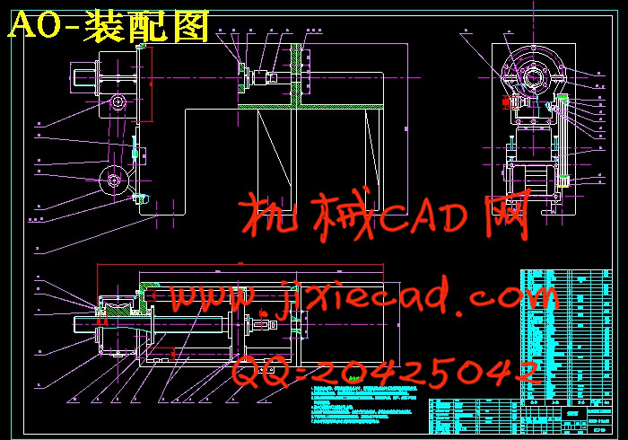
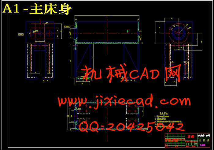
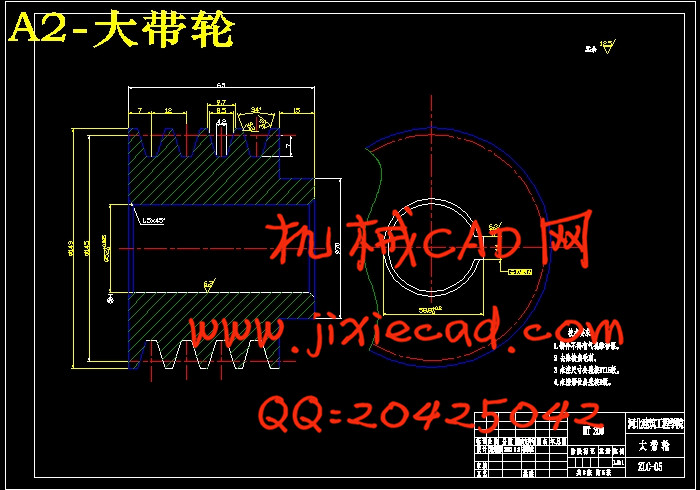
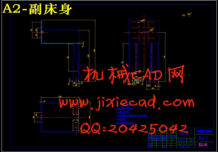
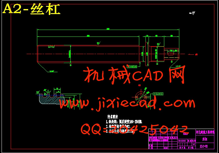
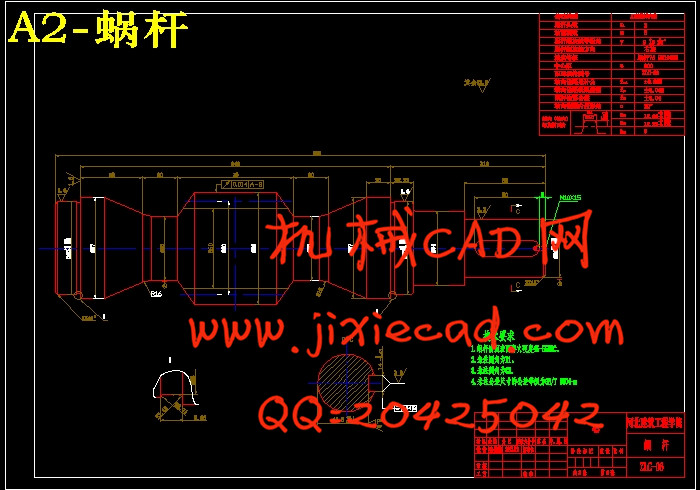
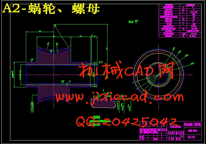
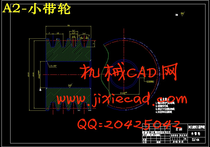
本文介绍的是自制20T拉床的设计。拉床是用拉刀加工工件各种内外成型表面的机床。拉削时机床只有拉刀的直线运动,它是加工过程的主运动,进给运动则靠拉刀本身的结构来实现。专业化的拉床也预示着它的高价位,而且有时不需要那么高的精度要求,而使用这些拉床无疑是种浪费。这就需要工厂内部自己制造一些简单的,可以完成大部分加工的拉床。而自制拉床无疑是个好的选择,它的结构很简单,用材很少可以选择一些标准件来组装,部分不是标准件的地方自己工厂内部加工制造也很容易。因而成本很低,对于中小型企业来说是最好不过的选择了。本文中的自制拉床是一种主要用于拉削零件内孔、键槽的小型机械式拉床。结构主要由床身、动力机构、传动机构、附属装置等组成。它主要是由皮带传动、蜗轮蜗杆减速器、滑动丝杠螺母传动来完成拉削工作的。本设计结构合理,生产成本低,效率高,满足工作性能,而且操作方便。
关键词:自制 拉床 蜗轮蜗杆 滑动丝杠
Abstract
This article describes the design of self-made 20T broaching machine. Broaching machine is a machine which using the pulling knife to processing various internal and external surface molding. Broaching machine only has the linear motion of the broach, which is the main movement processing, feed movement by pulling the knife is to achieve the structure itself. Specialized broaching machine also indicates that its high price, and sometimes it does not require so much high precision, and the use of these types of broaching machine is also a waste. This requires its own factory can manufacture a few simple and can finish most of the broaching processing machines. The self-made broaching machine is without doubt a good choice, its structure is very simple, very little timber ,and it can choose a number of standard parts to the assembly. Although some parts are not standard parts of their factory, the processing is also very easy. And therefore low cost for small and medium enterprises is the best choice. Broaching machine in this article is mainly used for the aperture broaching, keyway broaching. It’s composed mainly by the bed structure, power agencies, transmission, ancillary part and so on. It mainly uses the leather belt drive,worm reduction gear ,glide screw nut drive to complete the broaching work. This design has rational structure, low cost, high efficiency, good performance, and easy to operate.
Key words: self-made broaching machine worm gear glide screw nut
目录
第一章 前言 ……………………………………………………………………… 1
第二章 总体设计………………………………………………………………… 3
2.1设计任务 ……………………………………………………………………… 3
2.2 设计目的……………………………………………………………………… 3
2.3研究方法、思路 ……………………………………………………………… 4
2.4 设计题目分析 ………………………………………………………………… 4
2.5 总体布置简图 ………………………………………………………………… 5
第三章 螺旋机构的设计………………………………………………………… 7
3.1 耐磨性计算 …………………………………………………………………… 7
3.2 验算自锁条件 ………………………………………………………………… 10
3.3 校核强度 ……………………………………………………………………… 10
3.4 螺杆稳定性计算 ……………………………………………………………… 14
3.5螺杆刚度计算 ……………………………………………………………………14
第四章 带传动设计计算 ………………………………………………………… 15
4.1 设计功率 ………………………………………………………………………15
4.2选定带型 …………………………………………………………………………15
4.3带传动传动比 ……………………………………………………………………15
4.4带轮直径 …………………………………………………………………………15
4.5实际转速 …………………………………………………………………………16
4.6 带速 ………………………………………………………………………………16
4.7 轴间距设计计算 ……………………………………………………………… 16
4.8 V带的根数……………………………………………………………………… 17
4.9 单根V带的预紧力 …………………………………………………………… 18
4.10 带轮的结构尺寸 ……………………………………………………………… 18
第五章蜗轮蜗杆的设计计算 …………………………………………………… 19
5.1 蜗轮蜗杆的类型、特点………………………………………………………… 19
5.2 蜗轮蜗杆的设计计算…………………………………………………………… 21
第六章 螺母和蜗轮凸缘的强度计算 ………………………………………… 25
第七章 夹具的结构及性能分析 ……………………………………………… 27
第八章 拉床的电气控制系统的设计…………………………………………… 29
8.1 控制系统总体方案的确定 ……………………………………………………… 29
8.2 行程开关 ………………………………………………………………………… 29
8.3 主控制系统………………………………………………………………………30
第九章 轴承的选择与计算 ………………………………………………………31
9.1轴承的选择 ………………………………………………………………………31
9.2 轴承的构造 ………………………………………………………………………31
9.3 轴承的类型 ………………………………………………………………………32
9.4 滚动轴承选型和校核 ……………………………………………………………33
9.5 滚动轴承的寿命计算 ……………………………………………………………35
第十章 传动、减速装置的润滑…………………………………………………37
第十一章 轴的校核 ……………………………………………………………… 40
第十二章 机架的分析与设计……………………………………………………41
11.1 机架的分类 ……………………………………………………………………41
11.2 机架的设计准则 ………………………………………………………………42
11.3 机架设计的一般要求 …………………………………………………………43
11.4 机架设计步骤 …………………………………………………………………44
11.5机架的结构选择 ……………………………………………………………… 45
11.6 机架选用的材料……………………………………………………………… 46
设计小结 ……………………………………………………………………… 47
参考文献 …………………………………………………………………………… 48


