设计简介
摘要
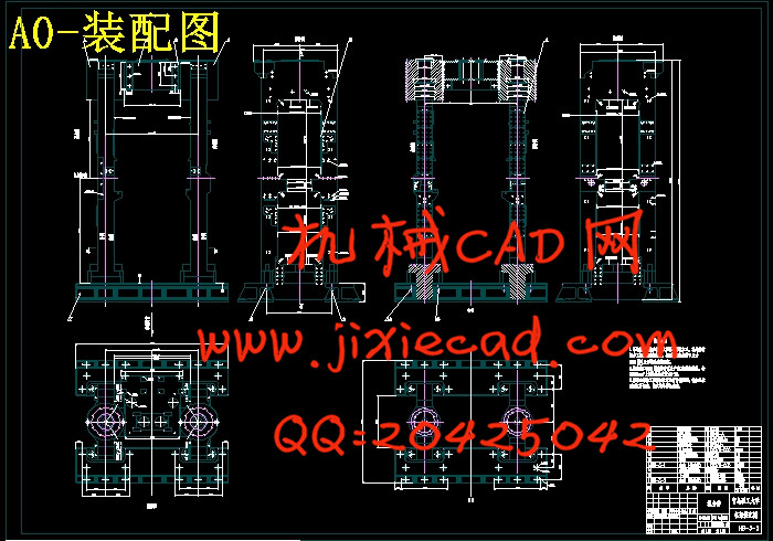
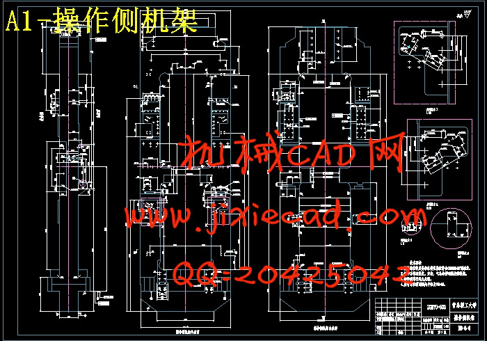
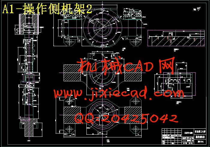
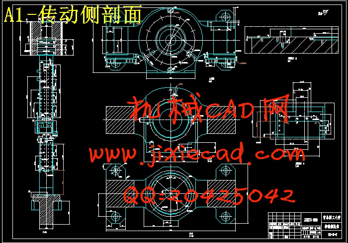
本轧机为厚板轧机,重点设计了机架部分。机架是轧钢机的重要部件,用来安装整个辊系及轧辊调整装置,并承受全部轧制力。因机架重量大,制造复杂,一般给予很大安全系数,并作为永久使用的不更换零件来进行设计,因此机架必须有足够的强度和刚度,以保证其应力分布均匀、变形尽可能小。由于轧机机架比较复杂、不规则,一般采用采列柯夫计算方法进行闭式机架的强度和变形计算然后采用有限单元法校核机架的应力、变形及安全系数。在以往机架的设计中,安全系数取得很高但仍不能保证机架的可靠工作,机架的破坏多在压下螺母孔、机架窗口转角处等压力集中大的部位,采列柯夫计算方法只能求得某些部位的应力值,而有限单元法能求出整个机架多部位的应力场,对其进行模拟计算,得出机架最危险的地方和应力分布规律,获得其变形,计算出轧机机架的刚度。
关键词:厚板轧机、轧机机架、采列柯夫、有限单元法
Abstract
This mill is heavy plate mill. Frame is the important component to mill roll system and install the device, and roll all rolling force. Because big weight, manufacturing complex frame, give great safety coefficient, and as a permanent use no replacement parts for design, thus frame must have enough intensity and stiffness, in order to ensure its deformation, stress distribution uniformity as small as possible.Due to the complicated mill frame, use commonly irregular KeFu listed mining method for calculating the strength and deformation of the closed frame is calculated by using the finite element method and the stress and deformation of the checking frame and safety coefficient. In the previous frame design, high safety coefficient made but still can't ensure reliable work, the frame of destruction in frame under the frame window corner, nut pressure concentration, part of the big KeFu column calculating method for certain parts of the only stress value, and finite element method can be more parts of the entire frame, carries on the field simulation, draw frame's most dangerous place and stress distribution obtained and the deformation, calculate mill frame stiffness.
Keywords: heavy plate mill, KeFu column frame, the finite element method
目录
摘要 1Abstract 2
目录 3
前言 1
第一章 总论 2
1.1 概述 2
1.1.1 我国中厚板轧机发展历史 2
1.1.2 目前我国主要中厚板生产设备情况 2
1.1.3 我国中厚板轧机将出现快速发展 6
1.2 厚板轧机生产线的生产工艺 8
1.3 轧钢技术的发展前景 10
第二章 设计方案的确定 13
2.1 工作制度 13
2.2 主转动方式 14
2.3 压下装置的结构形式 15
2.4 上辊平衡装置 16
2.5轧机机架 16
2.6 设计方案的确定 17
第三章 专题设计计算部分 17
3.1设计题目及要求 17
3.2轧制过程变形区及其参数 17
3.3原始数据 18
3.4主要参数的确定 19
3.5咬入条件的校验 21
3.6轧制力计算 21
3.7轧制力在接触弧上作用点的位置 22
3.8轧制力矩的计算 22
3.9轧机主电动机功率的确定与选择 25
3.10机架的基本尺寸及校核 26
3.10.1机架的类型及结构 26
3.10.2 机架的主要结构参数 27
3.10.4机架强度计算 29
3.10.5机架的变形计算 34
3.10.6机架刚度的计算 36
3.10.7用弹性力学有限单元法计算机架的应力和变形 37
总结 40
致谢 41
参考文献 42


