设计简介
摘要
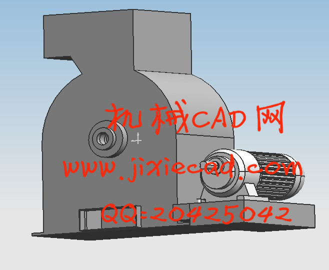
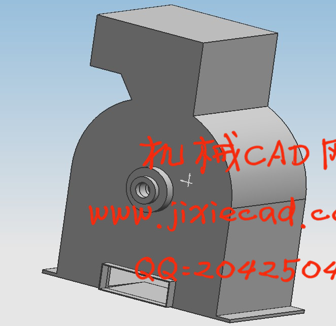
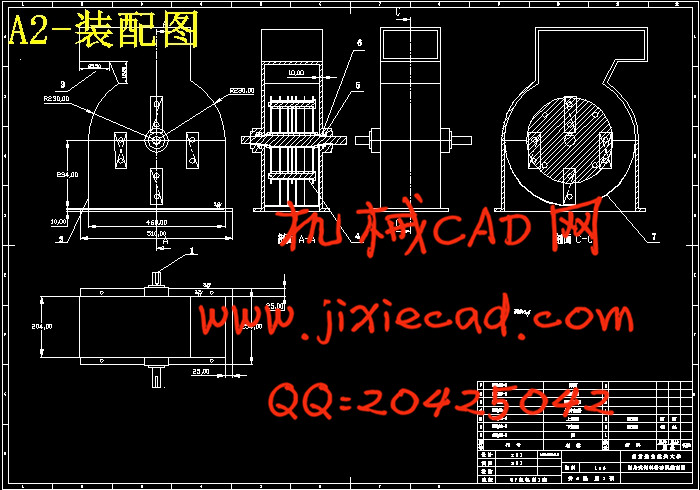
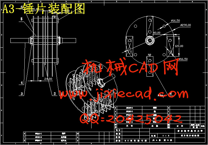
锤片式粉碎机是饲料加工机械的四大主机之一,是饲料生产必要的设备之一,其性能对饲料厂的节能降耗意义重大。分析了锤片式粉碎机的结构特点,设计出满足要求的锤片式粉碎机。建立了锤片式粉碎机转子的离散化模型,利用ADAMS软件术对锤片对称交错排列形式的粉碎机转子进行动力学仿真分析,得到了与实际情况相近的结论。仿真结果表明,锤片对称交错排列转子的平衡性较好,其中交错排列转子两端轴承承载情况相近,转子稳定性好。转子是锤片式粉碎机的主要工作部件。利用ug对锤片式粉碎机转子中的各零件进行三维建模、虚拟装配、模型分析和动态仿真。设计者可以充分利用ug单一数据库管理技术,通过改变尺寸参数来方便地修改和更新零件,还可以直观地观察和分析转子的外形、零件间的相互位置关系和运动状态。关键词:振动;仿真;锤片式粉碎机;ug;转子;三维建模
Abstract
Hammers mill, which is one of the four main feed processing machineries and one of the necessary equipment of feed processing, has a great influence on economy energy sources in feed factory. In this paper the structural features of the hammers mill are analyzed. The statics and the vibration characteristic of its frame are investigated with the ADAMS software. A discrete model of hammers mill's rotor was set up. Mill's rotor arranged in different hammer forms was analyzed by way of dynamic simulation with virtual prototype technology. The result that is similar to facts was deduced. The conclusion indicated that the rotor with interlaced or symmetry-interlaced hammer form has better balance and the former is with good stability because of its equal load on each bearing. Rotor is an important assembly of hammers mill. This research utilized Pro/E to carry out three-dimensional modeling of the parts of hammer mill’s rotor, virtual assemble, model analysis, and motion emulation. Designers can modify the parts easily by changing size parameters, and also can observe forming, position relation of parts and motion state of the rotor.
Key words: Vibration;Simulate;hammers mill;ug;rotor;3D modeling
目录
摘要 IKey words: Vibration;Simulate;hammers mill;ug;rotor;3D modeling
目录
Abstract II
1 综 述 3
1.1 课题的目的和意义 3
1.2 国内外锤片式粉碎机发展概况 4
1.2.1国外锤片式粉碎机发展概况 4
1.2.2我国粉碎机械发展概况 10
1.3、我国粉碎设备的发展趋势 15
2 锤片式粉碎机的设计 16
2.1 锤片式粉碎机的主要结构 16
2.2.电动机、传动方案选择确定及设计计算 17
2.2.1转子直径D与粉碎室宽度B的确定 17
2.2.2 配套功率N的确定 18
2.2.3. 传动装置的总体设计 19
2.2.4 V带及带轮的设计计算 20
2.3转子的设计 34
2.3.1 轴的结构设计 34
2.3.2 锤片的设计 36
2.3.3锤片的排列方式 38
2.3.4 锤架板 41
2.3.5套筒的设计 42
2.4 机架、机壳、输送装置及进、出料口设计 43
3 零件强度校核 44
3.1轴的强度校核 44
3.1.1 求轴上的载荷 44
3.2 轴承寿命校核 50
3.2.1求比值 51
3.2.2初步计算当量动载荷P 51
3.2.3验算轴承寿命 52
3.3键的选择及校核计算 52
4 基于Pro/E的转子三维实体造型 54
4.1主轴 54
4.2 锤片 55
4.3 套筒、锤架板 55
4.4 锤片隔套、销轴 57
4.5 转子的虚拟装配 58
5 清洗装置三维造型 59
6 总结与建议 60
6.1总结 60
6.2建议 61
参考文献 62
致 谢 63


