设计简介
摘 要
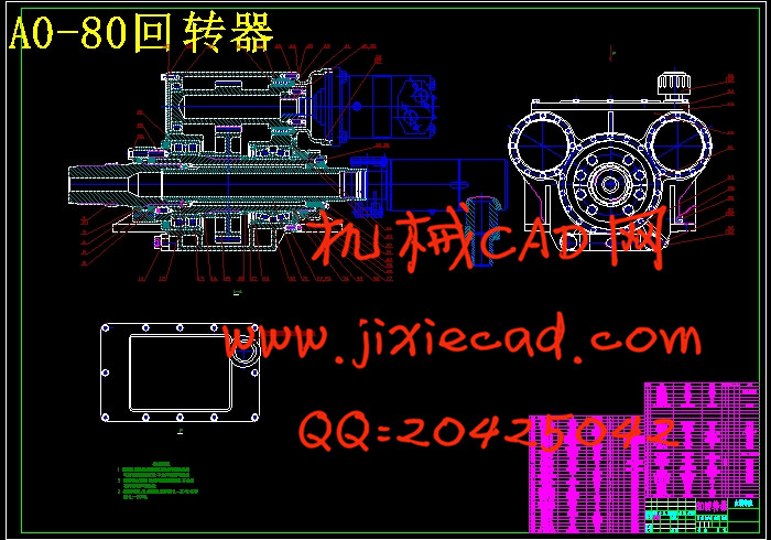
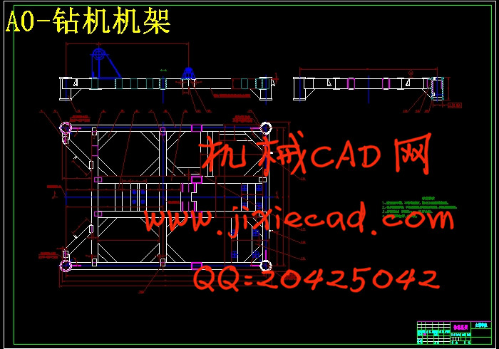
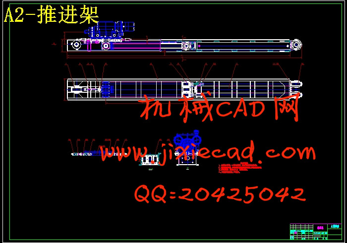
履带式锚固钻机组要是由回转器、 推进架、钻机步履机构、钻机机架、钻机操纵台管路等相应的部件组成。履带式锚固钻机组要用于目前地铁、高层建筑、机场及其他需要深基坑进行锚固、旋喷、降水等相应的作业。在此次的论文课题中,我在屠德刚老师的指导下,对钻机的结构布局、其动力回转结构、液压系统的运作等方面有了很大的认识,通过CAD等制图软解的辅助,更加形象的刻画了履带式锚固钻机的总体以及液压系统,通过资料的查询,对其动力系数和相应的各项参数指标了解有着本质的提升。在分析运动及设计结构时,要把产品的外型也要考虑在钻机设计中。通过这几个月的学习、查询本人熟悉了解履带式锚固钻机的工作原理以及各部件,了解其组成、如何工作及连接关系,对各部件的材质有了相应的了解。做到了钻机布局合理美观、安装使用方便。
关键词: 履带式锚固钻机 钻机步履机构 液压系统
Abstract
Rawler type anchor drill unit if the gyrator, propulsion, drill steps institutions, drill rack, drill control console of corresponding parts such as pipeline. Crawler type anchor drill unit to be used for the subway, high building, airport and other need to anchor deep foundation pits, jet grouting, precipitation, etc. The corresponding operations. In the thesis topic, I under the guidance of the teacher Tu, structure layout, the power of drilling rig rotary structure, hydraulic system's understanding of the operational aspects had the very big through CAD and other drawing soft solution of the auxiliary, more image depicts the crawler anchorage overall as well as the hydraulic system of drilling rig, through the data query, the power coefficient and corresponding parameter indicators to know has the nature of ascension. On the analysis of the movement and structure design, to product appearance also want to consider in the rig design. Through this a few months of learning, inquiry I understanding of crawler anchor drilling machine working principle and parts, understand its composition, how to work and connection relationship, have the corresponding knowledge of parts material. Did it drill rational layout and beautiful, easy installation and use.
Keywords: Caterpillar anchoring drill rig Drill steps institutions The hydraulic system
目 录
摘 要 V
Abstract VI
目 录 VII
1 绪论 1
1.1 钻机主要用途 2
1.2、主要技术参数 3
13、主机垂直状态:3200×2200×5000 4
2 钻机的总体传动设计 5
2.1、总体传动设计 5
3 动力头(回转器)设计 8
3.1. 动力头介绍 8
3.2. 设计要求 8
3.3 设计步骤 8
3.4 设计方案的分析与确定 8
3.5 主要零部件的结构及其选用 9
3.5.1. 各轴在动力头中的位置 9
3.5.2. 轴的结构设计 9
3.5.4. 轴的支承方式及轴承的选用 9
3.6 设计及校核 10
3.6.1 功率及转速计算 10
3.6.2 齿轮校核 10
3.7 典型工艺编制 13
3.7.2 箱体(MDL80D-2-33) 16
4 液压设计计算及说明 18
4.1 液压原理的设计 18
4.1.1 加压提升油路设计思路 18
4.1.2 起塔油路的设计思路 18
4.1.3 支腿油路的设计思路 18
4.1.4 主油路的设计思路 18
4.2 液压系统的计算 19
4.2.1 实际参数的计算 19
4.2.2 液压系统中主油路的校验 26
4.3 热平衡计算 29
4.3.2 双联泵 CBTL-F410/F410-AFP 30
4.3.3 小泵 CBW-F203-AFP 31
5 泵站的设计 32
5.1 泵站的介绍及作用 32
5.2 泵站的组成 32
5.2.1 油泵及电动机 34
5.2.2 散热器 34
5.2.3 油箱 34
5.2.4 空气滤清器 36
5.2.5 过滤器 36
6 操纵台的设计 37
6.1 操纵台的介绍及作用 37
6.2 设计要求及步骤 37
7 管路附件 42
7.1 油管的种类及选择 42
7.1.1 油管的种类 42
7.1.2 油管的选择 42
8 推进架中油缸的设计 46
8.1油缸设计要点 46
8.2设计要求: 46
8.3加压提升油缸主要尺寸的确定: 47
9 结论与展望 50
9.1 结论 50
9.2 展望 50
致谢 51
参考文献 52


