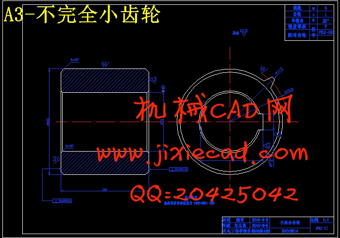
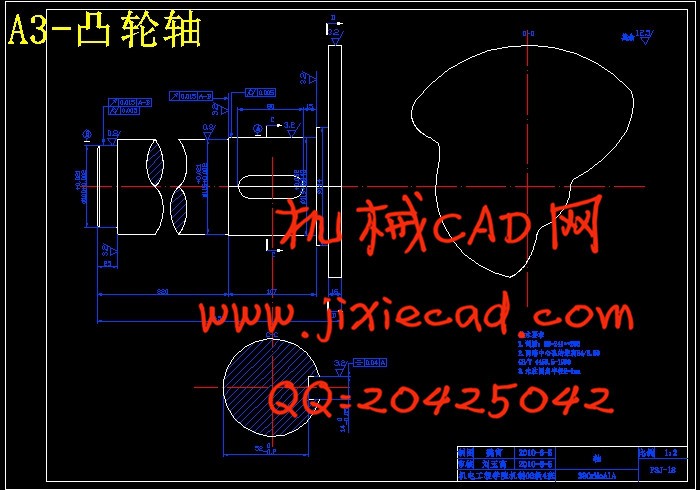
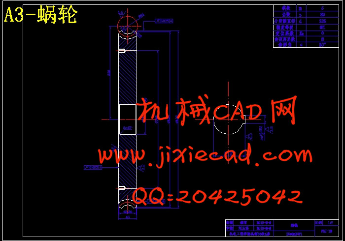
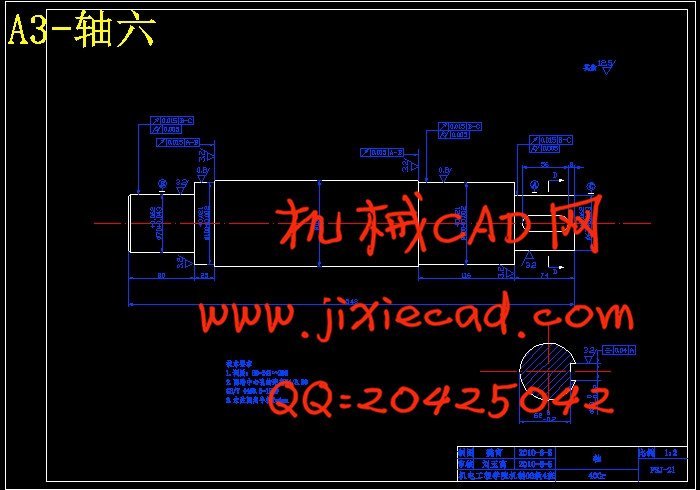
设计简介
抛砂机的设计
摘 要
抛砂机是解决单件、小批生产造型(型芯)行之有效的设备。抛砂机使用得当时,沿砂箱在高度上的紧实度比较均匀,也不需要补充夯实,紧实度高,而且抛砂机与某些其他造型机械相比振动小,噪声也小。
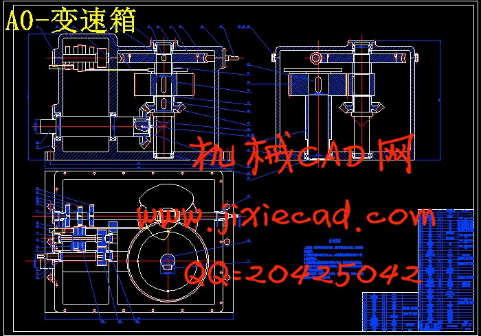
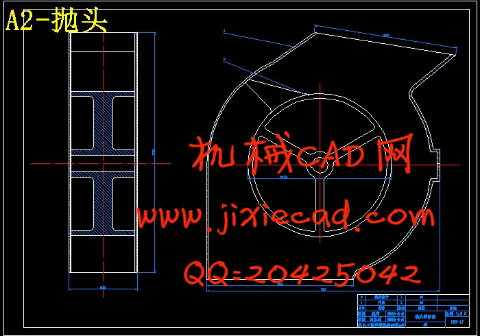
本次设计在研究普通抛砂机的结构及优缺点的基础上,设计出一台抛头固定砂箱运动的自动抛砂机,并且在抛头部分加装一变速装置使之能够在型砂高度增加时抛头转速相应增大,以改善型砂紧实力随型砂高度增加而相对减小的情况。该方案采用了凸轮的时需控制功能以实现抛头转速随着生产过程不断增快并且能够在最后自动返回,这种设计能够完全满足造型的紧实力要求,提高了造型的质量。
关键词:铸造技术;型砂紧实力;抛砂机
Design of Sand Slinger
Abstract摘 要
抛砂机是解决单件、小批生产造型(型芯)行之有效的设备。抛砂机使用得当时,沿砂箱在高度上的紧实度比较均匀,也不需要补充夯实,紧实度高,而且抛砂机与某些其他造型机械相比振动小,噪声也小。
本次设计在研究普通抛砂机的结构及优缺点的基础上,设计出一台抛头固定砂箱运动的自动抛砂机,并且在抛头部分加装一变速装置使之能够在型砂高度增加时抛头转速相应增大,以改善型砂紧实力随型砂高度增加而相对减小的情况。该方案采用了凸轮的时需控制功能以实现抛头转速随着生产过程不断增快并且能够在最后自动返回,这种设计能够完全满足造型的紧实力要求,提高了造型的质量。
关键词:铸造技术;型砂紧实力;抛砂机
Design of Sand Slinger
The sand slinger is an efficient equipment for the producing of the single unit model (core) in small batch. When the sand slinger is used appropriately, it is quite even in degree of ramming along the flask in altitude, and the degree of ramming is high without supplementing the ramming. Moreover,the noise of the sand slinger is smaller compared with certain other modelling machinery .
This program is based on the ordinary sand slinger's structure and its advantages and disadvantages. It is made to be an automatic sand slinger with a moving sandbox but fixed throws, and adding a gearbox to throw head to enable it to speed up correspondingly when the molding sand increases highly, to improve the situation that the molding sand reduces its tight strength along with the molding sand increase highly. This plan can achieve the first toss ever increasing speed with the faster production process with the cam’s timing control and can automatically return at last. This kind of design can completely satisfy the shape of the tight power requirements and improve the quality of modeling.
Key words: foundry engineering;molding sand tight strength; Sand Slinger
目 录
摘 要 І
Abstract П
1绪论 1
1.1 研究的目的和意义 1
1.2 国内外发展现状 1
2 方案论证 4
2.1 设计要求 4
2.2方案选择及分析 4
3 设计论述 7
3.1 抛头设计 7
3.1.1 抛头转速选择 7
3.1.2 抛头尺寸计算 7
3.2 工作台的设计 8
3.2.1 工作台尺寸设计 8
3.2.2 工作台与主轴箱间的连杆机构设计 9
3.2.3 强度校核 10
3.3 变速箱的设计 12
3.3.1 电机选择 12
3.3.2 V带和带轮的设计 15
3.3.3 传动部分第一级齿轮设计 16
3.3.4 传动部分第二级齿轮设计 19
3.3.5 Ⅰ轴上的蜗轮蜗杆设计 21
3.3.6标准直齿锥齿轮设计 24
3.3.7 不完全齿轮设计 27
3.3.8 Ⅲ轴(输出轴)的设计计算 29
3.3.9 Ⅱ轴(中间轴)的设计计算 33
3.3.10 Ⅰ轴(输入轴)的设计计算 37
3.3.11 Ⅳ轴(蜗轮轴)的设计计算 41
3.3.12 Ⅴ轴(凸轮轴)的设计计算 44
3.3.13 Ⅵ轴(锥齿轮轴)的设计计算 47
4 结论 51
4.1 设计总结 51
4.2 设计的缺点和不足 51
参考文献 52
致谢 53


