设计简介
摘 要
气动机械手是能模仿人手和臂的某些动作功能。它可代替人的繁重劳动以实现生产的机械化和自动化,能在有害环境下操作以保护人身安全,因而广泛应用于机械制造、冶金、电子、轻工和原子能等部门。
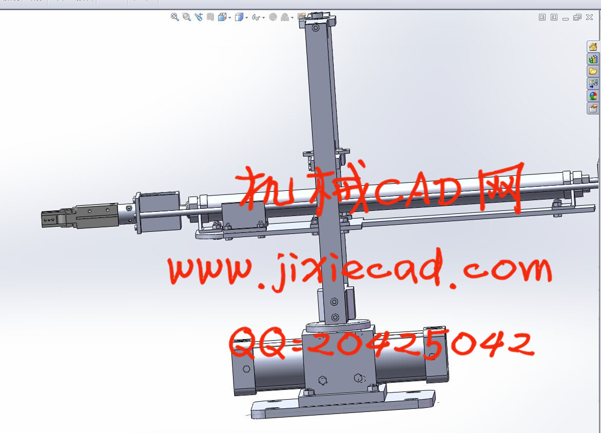
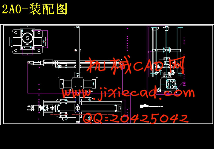
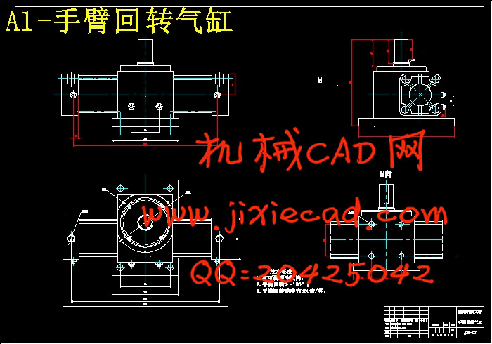
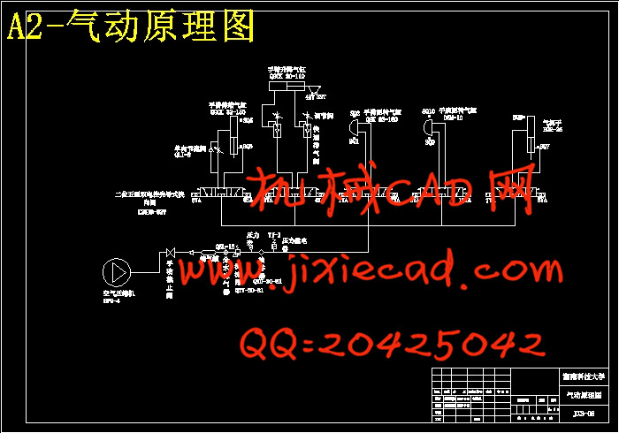
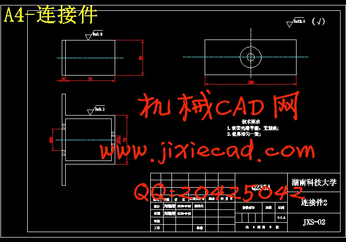
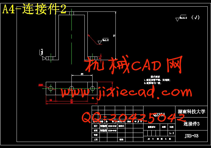
本文主要进行了气动机械手的总体结构设计、气动设计和运动设计。机械手的机械结构由气缸、气爪和连接件组成,可按预定轨迹运动,实现对工件的抓取、搬运和卸载。本次设计的机械手由五个气缸组成。手部驱动气缸、手臂伸缩气缸、手臂升降气缸、手腕回转气缸和手臂回转气缸。气动部分的设计主要是选择合适的控制阀,设计合理的气动控制回路,绘制气动原理图,通过控制和调节各个气缸压缩空气的压力、流量和方向来使气动执行机构获得必要的力、动作速度和改变运动方向,并按规定的程序工作。运动设计部分着重分析注塑机取件机械手的运动过程。
关键词:气动机械手;气动回路;气缸。
Abstract
Pneumatic manipulator is a automated devices that can mimic the human hand and arm movements to do something. It can replace the heavy labor in order to achieve the production mechanization and automation, and can work in dangerous working environments to protect the personal safety, Therefore widely used in machine building, metallurgy, electronics, light industry and atomic energy sectors.
This article is mainly of the pneumatic manipulator the overall design、 pneumatic design and movement design. This mechanism of manipulator includes cylinders and claws and connectors parts, it can move according to the due track on the movement of grabbing, carrying and unloading. The design of the manipulator is composed of five cylinder. Hand driven cylinder, telescopic cylinder and lift cylinder arm, wrist and arm rotating cylinder rotary cylinder. The pneumatic part of the design is primarily to choose the right valves and design a reasonable pneumatic control loop,Draw the pneumatic schematic diagram by controlling and regulating pressure, flow and direction of the compressed air to make it get the necessary strength, speed and changed the direction of movement in the prescribed procedure work.Motion design focusing on the analysis of vertical plastic injection machine dedicated manipulator motion process
Key word: pneumatic manipulator;pneumatic loop;cylinder;
目 录
第一章 绪论 1
1.1机械手国内外的发展趋势 1
1.1.1机械手国外发展趋势 1
1.1.2机械手国内发展趋势 2
1.2 应用机械手的意义 3
1.3 机械手的特点 4
1.4 机械手的工作原理 4
1.5 机械手的组成 4
1.5.1执行机构 5
1.5.2 驱动系统 6
1.5.3 控制系统 6
1.5.4 位置检测装置 6
1.6 机械手的分类 7
1.6.1按用途分 7
1.6.2 按驱动方式分 7
1.6.3 按控制方式分 8
第二章 注塑机取件机械手总体设计 9
2.1 机械手的座标型式与自由度 10
2.2 机械手的结构方案设计 10
2.2.1 手部结构方案设计 11
2.2.2 手腕结构方案设计 11
2.2.3 手臂结构方案设计 11
2.3 机械手的驱动方案设计 11
2.3.1 四种驱动方式介绍 11
2.3.2气压驱动优缺点 12
2.4 气动机械手的设计要求 12
2.5 注塑机机械手的主要技术参数 13
第三章 气压驱动系统设计 14
3.1 气动机械手概述 14
3.2 气动技术的发展与应用 14
3.2.1气动技术的发展历史 15
3.2.2我国气动技术的发展历史与现状 15
3.2.3气动技术的应用 15
3.3 气压驱动的特点 16
3.4 气压传动的组成 16
3.5 气源装置 17
3.5.1 动力源 17
3.5.2 空气压缩机 17
3.5.3容积式压缩机选择 17
3.6 压缩空气净化装置 18
3.6.1 后冷却器 18
3.6.2 油水分离器 19
3.6.3储气罐 19
3.6.4干燥器 19
3.6.5分水滤气器 19
3.6.6分水滤气器型号选择 19
3.7 辅助元件 20
3.7.1油雾器及其选择 20
3.7.2 消声器 20
3.7.3气液转换器 20
3.8 气缸与气缸马达 20
3.8.1气缸 20
3.8.2气缸马达 21
3.9 管路系统 21
3.10控制阀 22
3.10.1方向控制阀 22
3.10.2压力控制阀 23
3.10.3流量控制阀 24
3.10.4气压控制换向阀 24
3.10.5电磁控制换向阀 25
3.10.6时间控制换向阀 25
3.11控制阀的选择 25
3.12气压系统设计 25
3.12.1气压传动系统工作原理图 25
3.12.2 气压传动的工作原理 26
第四章 机械结构的设计 27
4.1 气抓手的选择 27
4.1.1 设计概述 27
4.1.2 夹紧装置的基本要求 27
4.1.3 夹紧气缸的夹紧、驱动力的确定 28
4.1.4 确定气缸直径与气缸作用力 29
4.2 手腕回转气缸的选择 30
4.2.1 设计概述 30
4.2.2 手腕驱动力矩的计算 30
4.2.3 腕部回转力矩的计算 32
4.2.4 手腕回转缸的尺寸及其校核 33
4.3 手臂伸缩气缸的选择 35
4.3.1 设计概述 35
4.3.2 设计参数 36
4.3.3 方案设计 36
4.3.4 尺寸校核 37
4.3.5 导向装置 37
4.4 手臂升降气缸的尺寸设计与校核 38
4.4.1 尺寸设计 38
4.4.2 尺寸校核 38
4.5 手臂回转气缸的尺寸设计与校核 39
4.5.1 气缸选型 39
4.5.2 尺寸设计 39
4.5.3 尺寸校核 40
4.5.4 气缸的主要零件材料 41
第五章 机械手工作顺序确定 42
第六章 结论 43
参 考 文 献 44
致谢 45


