设计简介
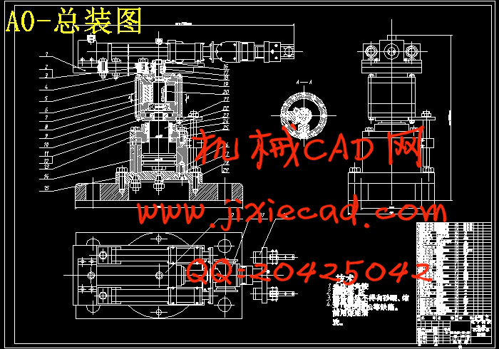
装卸工件机械手设计
摘 要
工业机器人自本世纪60年代初问世以来,已有80万余台用于世界各国的自动化生产线上,扮演着灵巧自如、不知疲倦“操作者”的角色,替代生产工人出色的完成极其繁重、复杂、精密或者充满着危险的各种各样的工作。不同用途的工业机器人正在工业生产中起到其它机器无法替代的作用。一般机器人由基座、腰、臂、腕和手五部分组成。腰和臂控制手的空间位置,腕控制手的空间姿态,而手则是实现对操作物体的抓放。本文设计的是装卸工件机械手,根据设计要求本文制定了一个由液压系统控制夹爪松开、夹紧物体的设计方案,对手部、腕部及整体的结构进行了设计,同时对其主要零部件进行了选择、设计和计算,内容包括液压系统的设计计算,轴的设计和校核,对设计的液压控制系统进行了分析与编程等。通过分析计算可以得出结论,此次设计基本满足设计要求。
关键词:装卸;工业机器人;机械手
The design of the manipulator for loading and unloading workpiece
Abstract
Since the beginning of 1960s, more than 800000 industrial robots have been used on automatic production lines of many countries all over the world, playing a role dexterous and as a free “operator” who has no sense of tireness. It can also accomplish various works that are very arduous and complicated or even full of danger instead of workers. The different application of industry robots to industrial production is playing an important role of which other machines are unable to take the place. The common robot basically consists of the waist, the arm, the wrist and the hand. Waist and arm control space position, while wrist controls special attitude, and the hand is used to realize grasping or putting objects. The design of this article is the mechanical arm of loading and unloading workpiece. According to the design requirements a schematic design has been developed with a hydraulic system controlling the claws from releasing and clamping objects, also it has been carried on the design to the structure of the hand, the wrist, and the whole. The contents including the selection of prime movers, design and check of gears, belts, and axes, the economic analysis to the feasibility of design proposal. Conclusions can be drawn through the computational analysis and this design can by and large meet the needs of the design request.
Key words:load and unload;Industrial robot ;manipulator
目录
1 绪论 1
1.1 选题的背景、目的和意义 1
1.2 机器人的发展概况 2
1.2.1 机器人的定义 2
1.2.3 国内机器人研究状况 4
1.2.4 国外机器人的最新发展 5
1.2.5 机器人目前研究热点及发展趋势 6
2手指部分的设计与计算 8
2.1夹紧机构的类型 8
2.2信息传感器 8
2.2.1内部信息传感器 9
2.2.2外部信息传感器 9
2.3液压传动的设计计算 10
2.3.1手爪夹紧液压传动的设计计算 11
2.3.2手爪回转液压传动的设计计算 12
2.4夹紧力的计算 14
2.4.1液压缸产生的推力及运动速度 14
2.4.2夹紧力的计算 16
3手腕部分的设计与计算 19
3.1确定油缸的工作压力 19
3.2确定经油缸的流量 19
3.3确定油泵所需电机功率 19
3.4液压缸的输出扭矩计算 20
4手臂部分的设计与计算 22
4.1手臂的作用和组成 22
4.2对设计手臂的要求 22
4.3手臂的结构 23
4.4手臂的设计计算 23
4.4.1确定油刚工作压力 23
4.4.2驱动力的设计计算 24
4.4.3偏重力矩的设计计算 26
5.机身的设计与计算 29
5.1机身升降液压转动的设计计算 29
5.1.1确定油缸的工作压力 29
5.1.2确定经油缸的流量 29
5.1.3确定油泵所需电机功率 29
5.1.4液压泵的校核 30
5.1.5活塞杆强度和稳定性校核 32
5.2机身回转液压转动的设计计算 33
5.2.1确定油缸的工作压力 33
5.2.2确定经油缸的流量 33
5.2.3确定油泵所需电机功率 34
5.2.4液压缸的扭矩计算 34
6.PLC控制 36
6.1PLC实现的功能 36
6.2PLC控制电路接线图 36
6.3PLC输入(I/O)点数的分配 37
6.4PLC输出(I/O)点数的分配 38
6.5PLC控制梯形图 38
6.5程序调试 42
6.5.1主程序调试 42
6.5.2手动操作子程序调试 42
6.5.3自动运行子程序调试 43
结论 44
致谢 45
参考文献 46


