设计简介
摘 要
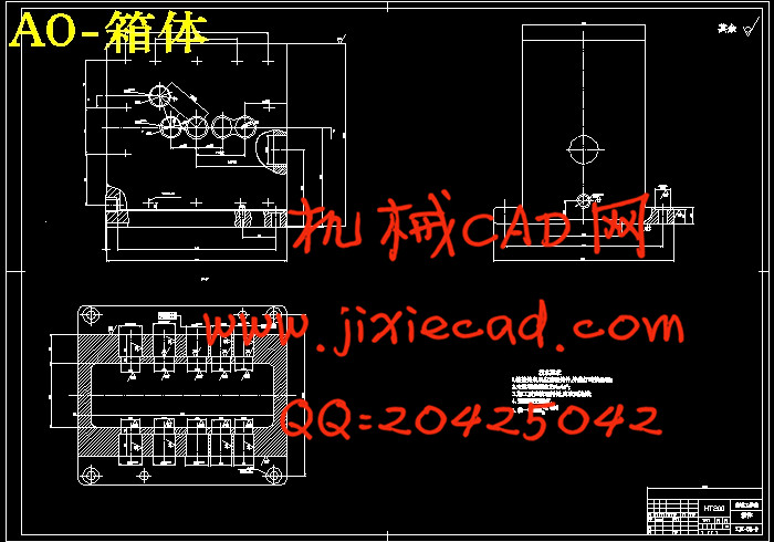
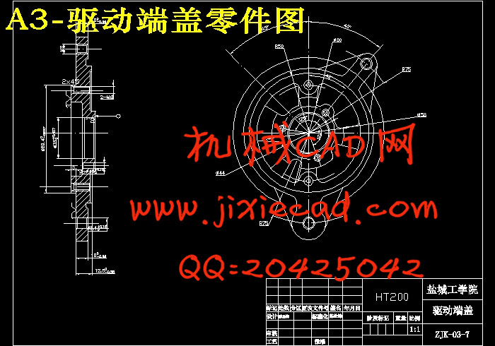
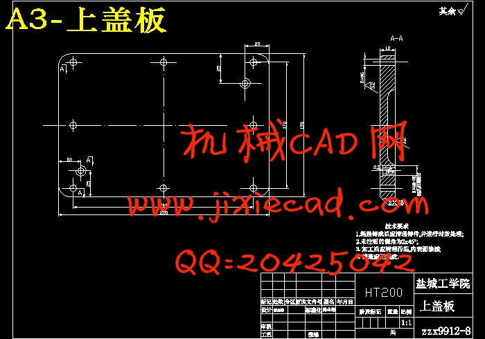
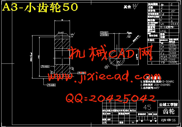
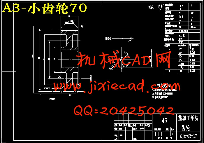
本文介绍了“电机驱动端盖多孔钻”专用机床的设计。它是在废旧的C6136车床的基础上进行改造的,目的是能将电机端盖上所要加工的孔在一道工序上全部完成,类似于组合钻床。它主要在钻头的动力传动系统和机床的夹具进行改造,可将传动箱安装在机床的床身上,夹具可安装在大拖板上。注意传动箱与机床主轴的连接,它可采用调整垫板保证三者等高性。其中必须考虑夹具在机床上怎么样定位、怎么样安装等问题以及传动轴的中心位置的排布。通过這些改进后,可以使机床能够适应新技术、新工艺的要求,适合于组成生产流水线。
经过查阅大量的相关文献资料,对原材料来源,水、电、气等能源供应,地理状况,地质状况和交通运输等作了充分的了解;同时还参观了盐城电机厂,并在那里进行了为期两个星期的实习,对该厂的生产状况和工艺流程布置都有了实质性的了解。因此,本设计具有一定的实用价值。
关键词:传动箱 车床 改造
Abstract
The machine tool special that the original introduced " the electrical machinery driving termination tops the multiple punching drill " design。That it is living reforms on the old and useless C6136's lathe base, The aim is top the electrical machinery extremity opening whic the combination drilling machine。Its main drill bit being living driving forceh processed being living completely to complete in one workman's sequence, It is analogous to drive system and the machine tool clamping apparatus is reformed, May fix the transmission case machine tool lathe bed on, The clamping apparatus may be fixed is living draging haul on the plank greatly。 Pay attention to the joint against the machine tool main shaft of transmission case, It may adopt and regulate spacer equal in height quality of guaranty。 In it we have to consider that the clamping apparatus is living how to locate on the machine tool, How installation and so on problem along with transmission shaft heart place line's fibaric。 Improve queen by means of these, May cause the machine tool can adapt to the fresh technique, Fresh technology demand, Be fit for giving birth to the pipleline to the component.
Keywords: Clamping apparatus Transmission case Lathe
目录
0前言………………………………………………………………………………1
1电机驱动端盖多孔钻专用机床的总体设计……………………………………3
1.1总体方案论证 ………………………………………………………………3
2计算部分…………………………………………………………………………4
2.1选择电动机……………………………………………………………………4
2.2 传动箱的设计…………………………………………………………………5
2.3 齿轮的 设计与较核……………………………………………………………6
2.4 轴的设计与较核………………………………………………………………9
2.5轴的设计计算及较核……………………………………………………………14
2.6定位销高度计算…………………………………………………………………15
2.7定位误差的计算…………………………………………………………………16
2.8夹紧力的计算……………………………………………………………………17
2.9偏心夹紧计算……………………………………………………………………18
3设计部分…………………………………………………………………………19
3.1夹具设计…………………………………………………………………………19
3.2家具设计的步骤…………………………………………………………………20
3.3传动箱的设计………………………………………………………………23
4样机和试件的各种试验及测试情况……………………………………………24
4.1机床空转运转试验………………………………………………………………24
5 预期效果…………………………………………………………………………25
6 结论………………………………………………………………………………26
7工作小结与致谢…………………………………………………………………27
参考文献……………………………………………………………………………28


