设计简介
摘 要
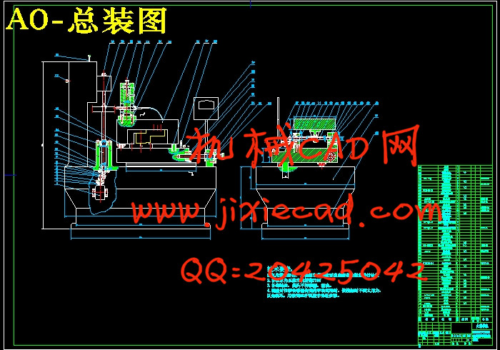
本次设计首先是对检测仪市场使用情况的数据进行采集工作,以确定设计的方案。其次,分析所具备的条件因素,考虑厂方的成组技术要求,进行方案的制定。
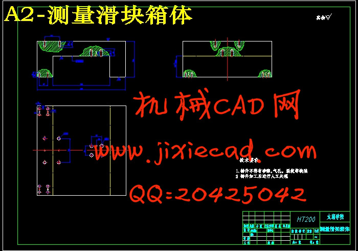
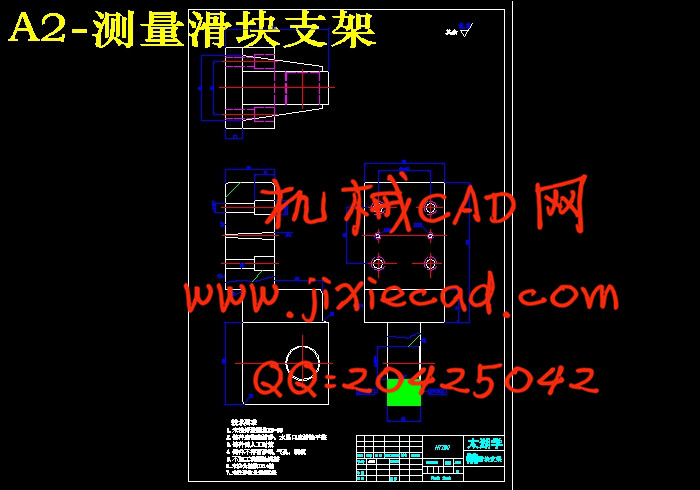
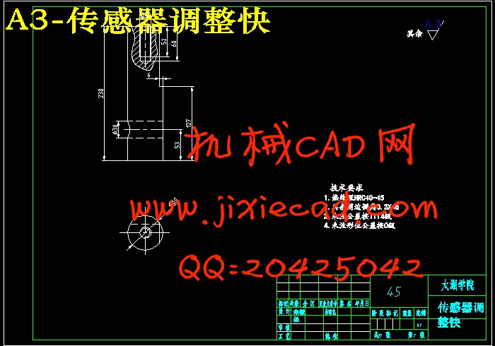
最后,开始零件设计和重要零件三维绘图设计。
本仪器用于测量直齿或斜齿的圆柱齿轮的渐开线齿轮误差。这种仪器不需要不同尺寸的基圆盘。通过在仪器上的数控装置可以将被测工件的基圆半径调准到0.002MM.仪器表有电感比较仪,其传感器将被测工件齿形的渐开线误差传到指示电表上。本课题主要是着重与仪器机械结构方面的设计,并制作相关的三维软件,以满足设计改进,质量控制,售后服务,商务洽谈方面的要求。
目前在国内产品中销量很多。国产齿轮测量中心的质量和性能不断提高,已经具有和国外产品竞争的能力。不过在仪器精度、稳定性,尤其在测量软件、仪器故障诊断功能等方面,和国外还有一定差距。
关键词:渐开线;仪器精度;数控装置;传感器
Abstract
This graduation design is first acquisition work on the use of market detector data, to determine the design scheme.Secondly, with analysis of factors, considering the requirements of group technology, make plan.
Finally, start part design and important parts of 3D graphics design.
This instrument is used for measuring the error of cylindrical gear involute spur or helical gear. This instrument does not need discs of different sizes. Through the numerical control device on the instrument can be measured workpiece radius of base circle aligned with the 0.002MM. instrument with inductance comparator, involute error of the sensor was measured the tooth profile of the workpiece to the indicating meter. This topic is mainly focuses on the design and equipment of mechanical structure, and fabrication of three-dimensional software related, in order to satisfy the design improvement, quality control, after sale service, business requirements.
At present in the domestic sales of many products. The quality and performance of domestic gear measuring center continuously improve, ability has competition and foreign products. But in the instrument accuracy, stability, especially in the aspect of software, measuring instrument fault diagnosis function, there is still a certain gap with foreign.
Key words: involute ;precision ;CNC device ; sensor
目录
Abstract IV
目录 V
1绪论 1
1.1 本课题的研究内容和意义 1
1.2国内外的发展概况 1
1.3本课题应达到的要求 2
2 设计的要求及基本技术规格 4
2.1 设计参数及要求
2.2 设计任务及工作量 4
2.3 设计内容 4
2.3.2 设计说明书,翻译英文资料 4
3 总体方案的设计原理 5
3.1 总体方案的确定 5
3.1.2 齿轮实际齿轮误差的测量 5
3.2 原有仪器示意图 6
3.3 总体方案的确定 6
4 机械部分的设计与说明 8
4.1 转动机构的设计 8
4.2 导向机构的设计 9
4.3 伺服驱动元件的设计 10
5 机械传动部分的设计 12
5.1 纵向导轨的选择 12
5.1.1 承受载荷的估算: 12
5.2 横向导轨的选择 13
5.3滚珠丝杠副的计算 13
5.3.2 额定动载荷
5.4稳定性验算 14
5.5 轴承的选择 17
5.5.1 寿命计算 17
5.5.2 计算附加轴向力 18
5.5.3 计算单个轴承的轴向载荷 18
5.5.4计算当量动载荷 18
5.5.5 寿命
5.5.6 额定静载荷验算 19
5.5.7 极限转速验算 19
5.6 联轴器的选择 19
5.7 键的选择与联接强度的计算 22
5.8 步进电机的选择 23
6 维护与保养 25
7 结论和展望 26
致谢 27
参考文献 29


