设计简介
摘 要
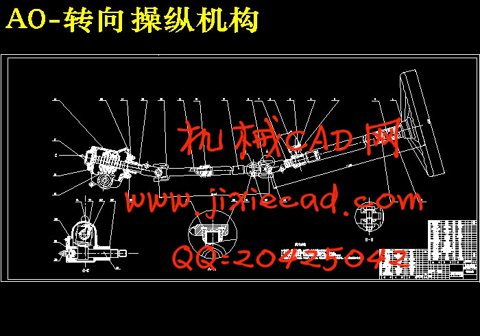
汽车在行驶的过程中,需要按照驾驶员的意志经常改变其行驶方向,即所谓的汽车转向。汽车的转向系统是一套用来改变或恢复汽车行驶方向的专用机构,本文的研究内容即是轻型货车的转向系统设计。
本文针对的是与非独立悬架相匹配的整体式两轮转向机构。利用相关汽车设计和连杆机构运动学的知识,首先对转向器,转向传动机构进行选择,接着再对转向器和转向传动机构进行设计,最后,利用软件AUTOCAD完成转向系统的设计图纸。
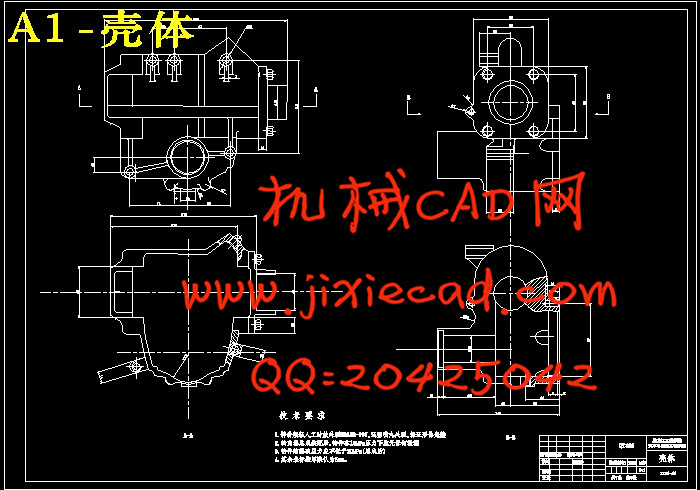
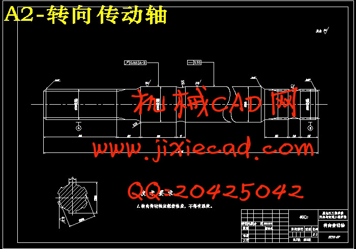
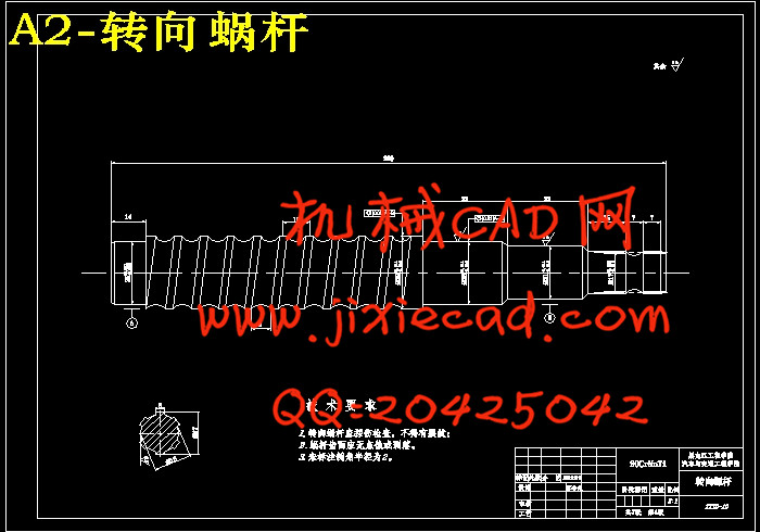
转向器在设计中选用的是循环球式齿条齿扇转向器,在对转向器的设计中,包括了螺杆—钢球—螺母传动副的设计和齿条—齿扇传动副的设计,前者是基于参照同类汽车,确定出钢球中心距,设计出一系列的尺寸,而后者则是根据汽车前轴的载荷来确定出齿扇模数,再由此设计出所有参数的。
转向梯形的设计选用的是整体式转向梯形,本文在设计中借鉴同类汽车转向梯形设计的经验尺寸对转向梯形进行尺寸初选。再通过对转向内轮实际达到的最大偏转角时与转向外轮理想最大偏转角度的差值的检验,和作为一个四杆机构对其最小传动角的检验,来判定转向梯形的设计是否符合基本要求。
本文在消化,吸收,总结,归纳前人的成果上,系统、全面地对机械转向系进行理论分析,设计及优化。为轻型汽车转向系的设计开发提供了一种步骤简单的设计方法。
关键词:转向系;转向器;转向梯形;传动副;结构元件
ABSTRACT
In a moving vehicle, the driver will need to frequently change its traveling direction, the so-called steering. Vehicle steering system is used to change or restore a car in the direction of a dedicated agency, the contents of this paper is the study of light vehicle steering system design.
This article is aimed at non-independent suspension and would like to match the overall style of the two steering. The use of the relevant vehicle design and kinematic linkage of knowledge, first of all, the steering gear, steering transmission choice, and then to the steering gear and steering transmission (mainly trapezoidal steering ) design, and finally, the use of AUTOCAD software and the Steering system to complete the design drawings.
Steering the ball of choice is the cycle of fan-type steering gear rack teeth, in the design of steering gear, including a screw - Ball - Vice-nut drive the design and rack - fan drive gear pair design, the former is based on the reference to similar vehicles, to determine the center distance of the ball, the design of a series of size, while the latter is based on the vehicle front axle load to determine the fan module out of gear, and then all of the resulting design parameters.
Steering linkage design is a whole selection of steering trapezoid, the paper design is used in car steering linkage from a similar experience in the design of the size of the steering linkage to the primary size. Through to the actual steering wheel in the maximum deflection angle with the steering wheel in the most ideal test of the difference of deflection angle, and four institutions, as a minimum transmission angle of its examination, to determine whether the design of steering trapezoid in line with the basic requirements.
In this paper, digestion, absorption, and summing up, summing up the results of their predecessors, the systematic, comprehensive mechanical steering system to carry out theoretical analysis, design and optimization. For the light vehicle steering system design and development provides a simple design method steps.
key words:Steering system;Steering gear;Steering trapezium;Transmission vice;Structural components
目 录
摘要...................................................................................................................................Ⅰ
Abstract.............................................................................................................................Ⅱ
第1章 绪论 .................................................................................................................1
1.1 转向系概述..........................................................................................................1
1.2 汽车转向系统的现状及发展趋势......................................................................1
第2章 汽车转向系方案的设计..............................................................................5
2.1 转向系主要性能参数.........................................................................................5
2.1.1 转向器的效率...........................................................................................5
2.1.2 传动比的变化特性 .................................................................................7
2.1.3 转向器传动副的传动间隙......................................................................10
2.1.4 转向盘的总转动圈数..............................................................................10
2.2 转向系的选择.....................................................................................................10
2.2.1 机械转向系..............................................................................................10
2.2.2 动力转向系..............................................................................................12
第3章 汽车转向器方案的设计.............................................................................14
3.1 机械式转向器的选择.........................................................................................14
3.1.1 齿轮齿条式转向器..................................................................................14
3.1.2 循环球式转向器......................................................................................14
3.1.3 蜗杆滚轮式转向器..................................................................................15
3.1.4 蜗杆指销式转向器..................................................................................16
第4章 汽车转向传动机构的设计.........................................................................17
4.1 转向传动机构的选择.........................................................................................17
4.1.1 与非独立悬架配用的转向传动机构......................................................17
4.1.2 与独立悬架配用的转向传动机构..........................................................18
4.2 转向梯形的选择.................................................................................................20
4.2.1 整体式转向梯形....................................................................................20
4.2.2 断开式转向梯形....................................................................................21
第5章 转向系的设计计算.....................................................................................23
5.1 转向器的结构型式选择及其设计计算...........................................................23
5.1.1 螺杆—钢球—螺母传动副的设计........................................................23
5.1.2 齿条、齿扇传动副的设计....................................................................27
5.1.3 循环球式转向器零件强度计算............................................................32
5.2 整体式转向梯形结构优化设计.......................................................................36
5.3 转向系结构元件...............................................................................................41
结论.................................................................................................................................44
参考文献........................................................................................................................45
致谢.................................................................................................................................46


