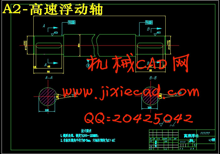
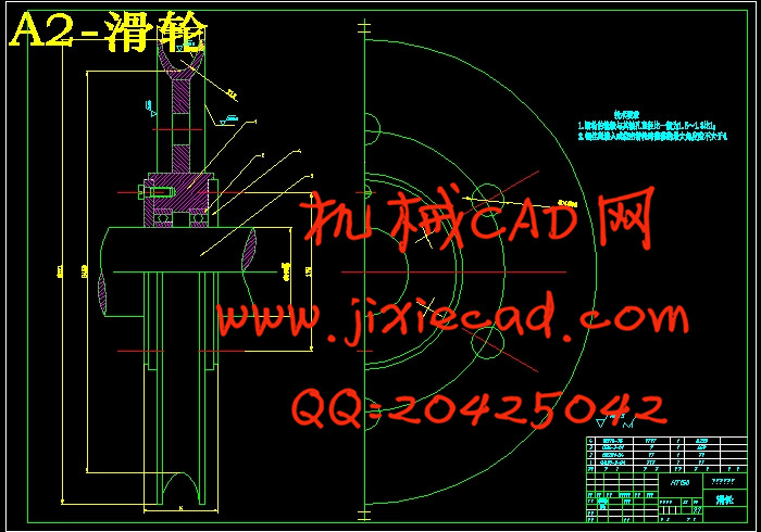
设计简介
摘 要
桥式起重机是一种提高劳动生产率重要物品搬运设备,主要适应车间物品搬运、设备的安装与检修等用途。我国生产的吊钩电动双梁桥式起重机额定起重范围为5~500t,一般10t以上,起重机有主、副两套起升机构;300t以上,起重机还有三套起升机构。
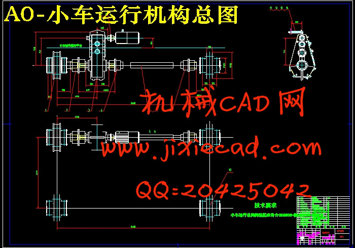
桥式起重机由桥架、小车运行机构、大车运行机构和电气设备构成。在系统整体设计中采用传统布局的典型结构,小车运行机构采用集中驱动。起升机构滑轮组采用双联滑轮组,重物在升降过程中没有水平移动,起升过程平稳,且钢丝绳的安装和更换容易。相应的卷绕装置采用单层卷筒,有与钢丝绳接触面积大,单位压力低的优点。在起升机构中还涉及到钢丝绳、减速器、联轴器、电动机和制动器的选择等。小车运行机构中涉及小车轮压计算、小车车轮、小车轨道、减速器、联轴器、电动机和制动器的选择计算等。
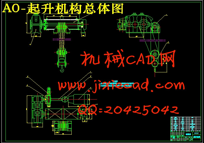
起重机是用来对物料做起重、运输、装卸和安装等作业的机械设备,它可以减轻体力劳动、提高劳动生产率和在生产过程中进行某些特殊的工艺操作,实现机械化和自动化。起升机构包括电动机、制动器、减速器、卷筒和滑轮组。电动机通过减速器,带动卷筒转动,使钢丝绳绕上卷筒或从卷筒放下,以升降重物。
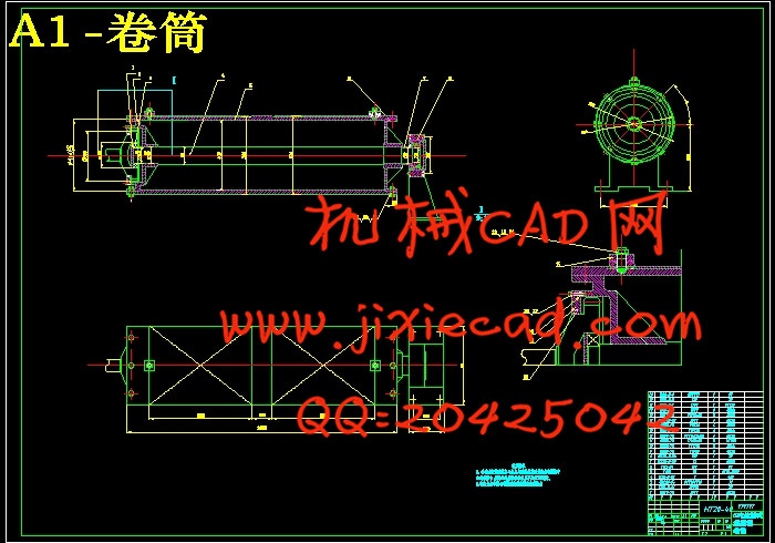
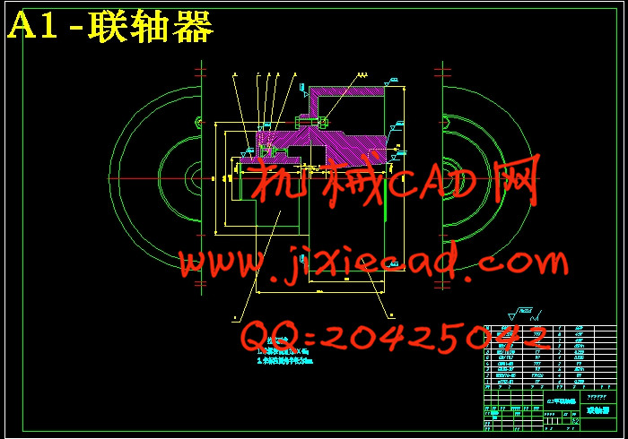
本文就十五吨桥式起重机起升机构做设计计算,确定起升机构传动方案,确定起升机构工作级别,对起升机构的主要部件卷筒、钢丝绳、滑轮等钢丝绳卷绕系统,电动机、联轴器、减速器等驱动装置进行设计计算,验证卷筒壁压应力,卷筒应力,确定吊钩装置构造方案,吊钩横梁,滑轮轴的计算等。对起升机构运行的过程,包括起升速度、起升和制动时间进行计算和验算。
关键词:桥式起重机;起升机构;小车运行机构;传动方案;卷绕系统;驱动装置;起升运行
ABSTRACT
Bridge crane is a significant increase labor productivity goods handling equipment, primarily to carry goods workshops, equipment installation and maintenance, and other purposes. China's production of electrical hook rated double-beam bridge crane lifting the range of 5 ~ 500 t, generally more than 10 t, cranes are the main, two sets of lifting300 t above, there are three sets of cranes lifting bodies.
Beam from the bridge crane, the trolley running, and traveling mechanism constituted. The overall design of the system using the traditional layout of the typical structure and operation of institutions used car driven focus. Pulley group or agency from using double-pulley blocks, heavy objects in the process of lifting the level of no movement, or from the process smooth, and the installation and replacement of wire rope easily. Winding installations in the corresponding single reel, a large area of contact with the rope, the advantages of low pressure units. In lifting bodies also involves rope, reducer, couplings, electrical and brake the choice. Vehicles involved in the operation of institutions pressure on the wheels, car wheels, car track, reducer, couplings, electrical and brake the choice of calculation.
Crane is used to start heavy materials, transportation, handling and installation of machinery and equipment and other operations, which can reduce manual labor, improve labor productivity and in the production process for some special process operation, mechanization and automation. Lifting mechanism includes a motor, brake, reducer, drum and pulley. Motor through reducer, driving drum rotation, so that the wire rope around the drum or from a roll down to lift heavy loads.
In this paper, fifteen tons crane hoisting mechanism to do the design calculations to determine the transmission scheme lifting mechanism, hoisting mechanism to determine the working level of the main components of the hoisting mechanism drum, wire rope, wire rope winding system pulleys, motors, United coupling, reducer drives the design calculations, validation reel wall stress, stress reel, hook device is configured to determine program, hook beams, pulley shaft calculation. Hoisting mechanism for running processes, including the lifting speed, lifting and braking time calculations and checking.
Keywords: bridge crane;hoisting mechanism;car agencies operating;transmission scheme; winding system; drive; lifting operation
目录
第一章 绪论 1Bridge crane is a significant increase labor productivity goods handling equipment, primarily to carry goods workshops, equipment installation and maintenance, and other purposes. China's production of electrical hook rated double-beam bridge crane lifting the range of 5 ~ 500 t, generally more than 10 t, cranes are the main, two sets of lifting300 t above, there are three sets of cranes lifting bodies.
Beam from the bridge crane, the trolley running, and traveling mechanism constituted. The overall design of the system using the traditional layout of the typical structure and operation of institutions used car driven focus. Pulley group or agency from using double-pulley blocks, heavy objects in the process of lifting the level of no movement, or from the process smooth, and the installation and replacement of wire rope easily. Winding installations in the corresponding single reel, a large area of contact with the rope, the advantages of low pressure units. In lifting bodies also involves rope, reducer, couplings, electrical and brake the choice. Vehicles involved in the operation of institutions pressure on the wheels, car wheels, car track, reducer, couplings, electrical and brake the choice of calculation.
Crane is used to start heavy materials, transportation, handling and installation of machinery and equipment and other operations, which can reduce manual labor, improve labor productivity and in the production process for some special process operation, mechanization and automation. Lifting mechanism includes a motor, brake, reducer, drum and pulley. Motor through reducer, driving drum rotation, so that the wire rope around the drum or from a roll down to lift heavy loads.
In this paper, fifteen tons crane hoisting mechanism to do the design calculations to determine the transmission scheme lifting mechanism, hoisting mechanism to determine the working level of the main components of the hoisting mechanism drum, wire rope, wire rope winding system pulleys, motors, United coupling, reducer drives the design calculations, validation reel wall stress, stress reel, hook device is configured to determine program, hook beams, pulley shaft calculation. Hoisting mechanism for running processes, including the lifting speed, lifting and braking time calculations and checking.
Keywords: bridge crane;hoisting mechanism;car agencies operating;transmission scheme; winding system; drive; lifting operation
目录
1.1 桥式起重机的简介 1
1.2 起重机械的发展 2
1.3 起重机械的特点 2
1.4 起重机械的组成 2
第二章 起升机构主要部件的设计计算 4
2.1主要参数 4
2.2确定起升机构传动方案 4
2.3 确定吊钩和滑轮组 6
2.4 钢丝绳的计算 7
2.4.1 钢丝绳所受最大拉力 7
2.4.2 钢丝绳允许的偏斜角 7
2.5 卷筒的计算 8
2.5.1 卷筒材料 8
2.5.2 卷筒直径计算 8
2.5.3 卷筒长度 8
2.5.4 卷筒壁压应力验算 9
2.5.5 卷筒应力验算 10
2.6 绳端固定装置的计算 11
2.7 取物装置 13
2.7.1 确定吊钩装置构造方案 13
2.7.2 吊钩主体结构的主要尺寸的计算 14
2.7.3 吊钩强度验算 14
2.7.4 吊钩弯曲部分断面A-A强度验算 15
2.7.5 吊钩弯曲部分断面B-B强度验算 16
2.7.6 推力球轴承的选择 17
2.7.7 吊钩横梁的计算 17
2.7.8 滑轮轴的计算 18
2.7.9 拉板的强度校核 20
第三章 起升运行机构设计 23
3.1 力矩的计算 23
3.1.1 平稳上升阶段 23
3.1.2 平稳下降阶段 24
3.1.3 上升起动阶段 25
3.1.4 下降制动阶段 26
3.2 电动机的选择 26
3.2.1 电动机的功率确定 27
3.2.2 验算电动机发热条件 27
3.3 减速器的选择 28
3.3.1 减速器传动比 28
3.3.2 减速器的选取 28
3.3.3 输出轴强度校核 28
3.4 起升速度和实际所需功率 29
3.4.1 实际速度 29
3.4.2 实际功率 29
3.5 制动器的选择 30
3.6 起升和制动时间验算 31
3.6.1 起动时间验算 31
3.6.2 制动时间验算 31
3.7 高速浮动轴的计算 32
3.7.1 疲劳计算 32
3.7.2 强度验算 33
第四章 小车运行机构的设计计算 36
4.1原始参数 36
4.2设计计算步骤: 36
4.2.1驱动方案初步确定 36
4.2.2车轮与轨道的选取 36
4.2.3运行阻力计算 37
4.2.4电动机的选择 38
4.2.5减速器选择 39
4.2.6联轴器的选择 40
4.2.7制动器的选择 42
4.2.8电机过载校验 43
4.2.9起动时间与起动平均加速度的校验 44
4.2.10运行打滑验算 45
4.2.11小车运行机构布局图 46
第五章 结论与展望 47
5.1 结论 47
5.2 展望 47
参考文献 48
致 谢 49


