设计简介
摘 要
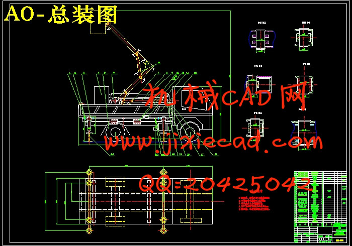
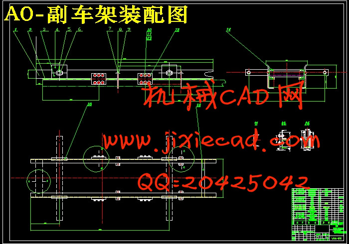
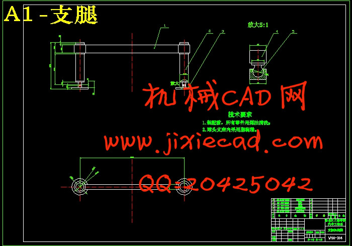
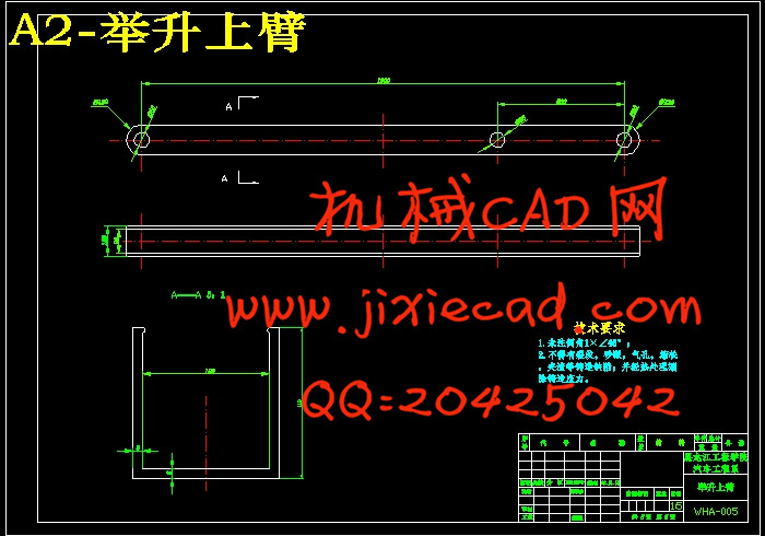
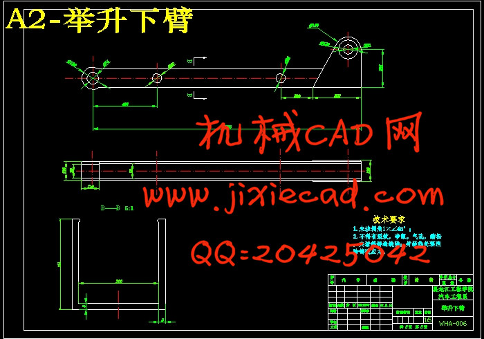
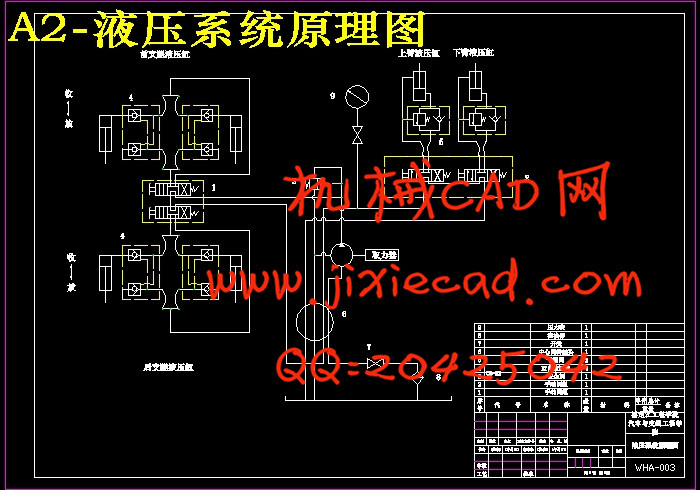
本设计主要以小型举升车改装结构为研究对象,对于副车架结构、上下臂进行结构和该车上的液压系统进行设计。主要分三部分进行阐述,第一部分:根据设计要求选择合适的二类底盘,对副车架进行设计及校核,确定副车架与车架的安装方式。最后画出副车架的总装图及零件图。第二部分:根据高空作业车的最大作业高度4.5m,在满足作业高度的前提下,进行高空作业臂的结构设计;首先根据工作载荷使用要求选择作业臂材料的类型;其次根据最大作业高度确定上下臂的长度;在经过受力分析利用强度来确定臂的截面尺寸及油缸的铰接位置;进而校核强度、刚度、稳定性,查看作业臂的尺寸是否符合要求。对施加均布载荷和约束,进行结构的强度和刚度分析,确定危险截面或危险点的应力分布及变形。最后画出作业臂总装图及上下臂零件图。第三部分:液压控制部分主要是指控制上下臂变幅运动的液压缸。文中详细记录了举升机构上臂液压缸和下臂液压缸的设计过程。在确定液压系统元件参数的基础上,完成了液压传动系统的设计计算,并作出液压系统图。
关键词:举升车;高空作业车;液压系统;支腿;液压缸。
ABSTRACT
This is designed to be small lift vehicles into the structure of the study, the sub-frame structure, upper and lower arm to the vehicle structure and hydraulic system design. Main component the same elaborate, part one : according to the maximum working height 4 aerial. 5mm , in meet job height of premise Xia , for aerial arm of structure design ; first under work load using requirements select job arm material of type ; second under maximum job height determine upper and lower arm of length ; in after by force analysis using strength to determine arm of section size and the oil cylinder of articulated location ; turn check strength , and stiffness , and stability , view job arm of size is meet requirements . To impose uniform load and constraint, strength and stiffness of the structural analysis to determine stress distribution and deformation of the dangerous section or so points. Last draw operations arm Assembly plans and parts of upper and lower arm. Part II : hydraulic control part mainly refers to the control arm of luffing motion up and down hydraulic cylinder. Aerial institutions the upper arm is recorded in detail design of hydraulic cylinder with hydraulic cylinders and lower arm. On the basis of determining parameters of hydraulic system components, completed the design and calculation of hydraulic system and hydraulic system diagram.
Key words: Lift car; Adrial work; Hydraulic pressure system ;Leg ; Hydraulic cylinder.
目 录
Abstract II
第1章 绪论 1
1.1研究背景 1
1.2 国内外研究现状 2
1.2.1国外研究现状 2
1.2.2国内研究现状 3
1.3研究课题的意义和目的 3
1.4 研究内容和方法 4
第2章 总体设计方案 6
2.1行走机构设计方案 6
2.2举升机构设计方案 6
2.2.1举升机构的概述 6
2.2.2举升机构方案的确定 7
2.3 本章小结 7
第3章 主要部件设计 9
3.1行走机构设计 9
3.2副车架的设计与校核 11
3.2.1副车架的概述 11
3.2.2副车架与车架的安装方式 12
3.2.3 U型螺栓和止推连接板的布置和选择 13
3.2.4车架强度校核 13
3.2.5主要零件制造工艺 14
3.3举升机构的设计 15
3.3.1材料的选择 15
3.3.2计算上、下臂的长度 16
3.3.3确定油缸铰点的位置 17
3.3.4上臂截面尺寸的确定 17
3.3.5下臂截面尺寸的确定 20
3.3.6连接处销轴尺寸的确定 24
3.4支腿机构的设计 25
3.4.1支腿跨距的确定 25
3.4.2支腿脚的设计 25
3.5本章小结 25
第4章 液压系统设计 26
4.1液压系统的构成 26
4.2液压系统设计概述 26
4.3设计依据 26
4.4主要机构简述 26
4.5主要工作机构液压回路的设计 27
4.5.1举升车变幅机构液压回路设计 27
4.5.2上臂油缸的设计计算 28
4.5.3下臂油缸的设计计算 32
4.6本章小结 35
结论 36
参考文献 37
致谢 39


