设计简介
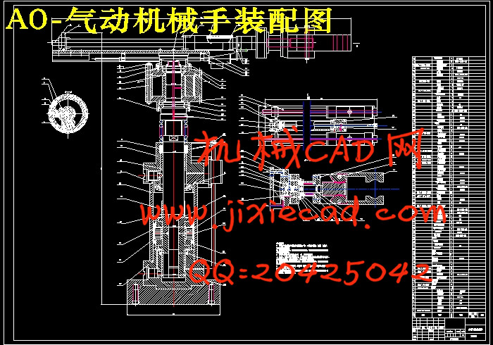
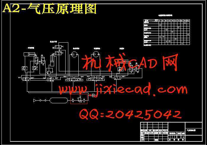
摘 要:本文主要进行了气动机械手的总体结构设计和气动设计。机械手的机械结构由气缸、气爪和连接件组成,可按预定轨迹运动,实现对工件的抓取、搬运和卸载。气动部分的设计主要是选择合适的控制阀,设计合理的气动控制回路,通过控制和调节各个气缸压缩空气的压力、流量和方向来使气动执行机构获得必要的力、动作速度和改变运动方向,并按规定的程序工作。气动机械手作为机械手的一种, 它具有结构简单、重量轻、动作迅速、平稳、可靠、节能和不污染环境等优点而被广泛应用。
关键词:气动机械手;气缸;控制阀;回路;设计
Abstract:This article mainly has carried on the overall structural design and aerodynamic design of pneumatic manipulator. Robot mechanical structure is composed of a cylinder, a pneumatic claw and a connecting piece, according to a predetermined trajectory, on a workpiece gripping, conveying and unloading. Pneumatic main part of the design is to choose appropriate control valve, the rational design of pneumatic control circuit, the control and regulation of each cylinder of compressed air pressure, flow and direction to the pneumatic actuator to obtain the necessary force, speed of action and change the direction of movement, and according to the prescribed procedures work.Pneumatic machinery as a manipulator, which has the advantages of simple structure, light weight, quick action, stable, reliable, energy saving and no pollution to environment has been widely used.
Key words: Pneumatic manipulator; cylinder; control valve; Circuit; the design
目 录
摘 要…………………………………………………………………………………1
关键词…………………………………………………………………………………1
1 前言…………………………………………………………………………………2
2 机械手的总体设计方案……………………………………………………………3
2.1 机械手的基本结构………………………………………………………………3
2.1.1 手部……………………………………………………………………………3
2.1.2 腕部……………………………………………………………………………4
2.1.3 臂部……………………………………………………………………………4
2.2 机械手基本形式的选择…………………………………………………………4
2.3 机械手的主要部件及运动参数设计……………………………………………4
3 手部的设计…………………………………………………………………………5
3.1 手部的基本要求…………………………………………………………………5
3.1.1 夹持式手部结构………………………………………………………………5
3.1.2 对手部的基本要求……………………………………………………………6
3.2 手部的结构设计…………………………………………………………………6
3.3 手部的计算………………………………………………………………………7
3.3.1 手指夹紧力的计算……………………………………………………………7
3.3.2 驱动力计算……………………………………………………………………7
3.3.3 气压缸直径计算………………………………………………………………7
3.3.4 缸筒壁厚的设计………………………………………………………………9
4 腕部的设计………………………………………………………………………10
4.1 腕部的基本要求………………………………………………………………10
4.2 腕部的结构设计………………………………………………………………10
4.3 腕部的计算……………………………………………………………………11
4.3.1 驱动力计算…………………………………………………………………11
4.3.2 液压缸压力验算……………………………………………………………12
5 臂部设计…………………………………………………………………………14
5.1 臂部的基本要求………………………………………………………………14
5.2 臂部的具体设计方案…………………………………………………………15
5.3 手臂伸缩的计算………………………………………………………………15
5.4 手臂升降的计算………………………………………………………………16
5.4.1 尺寸设计……………………………………………………………………16
5.4.2 尺寸校核……………………………………………………………………16
5.5 手臂回转气缸的计算…………………………………………………………17
5.5.1 尺寸设计……………………………………………………………………17
5.5.2 尺寸校核……………………………………………………………………17
6 气动系统设计……………………………………………………………………18
6.1 气动系统设计要求及选择……………………………………………………18
6.2 气压回路的选择………………………………………………………………19
6.2.1 各气压缸的换向回路………………………………………………………19
6.2.2 调速方案……………………………………………………………………19
6.2.3 缓冲回路……………………………………………………………………19
6.2.4 系统安全可靠性……………………………………………………………19
6.3 气压传动系统工作原理图……………………………………………………19
6.3.1 工作原理图…………………………………………………………………19
7 结论………………………………………………………………………………20
参考文献 ……………………………………………………………………………20
致 谢………………………………………………………………………………21


