设计简介
4座微型客货两用车设计
(后驱动桥、后悬设计)
摘 要
本设计为4座微型客货两用车的后驱动桥、后悬架设计。参照现有的生产技术水平,综合考虑生产成本,以及使用条件等多种因素, 经过收集各类型的后驱动桥、悬架的资料、实车观测和老师的指导,完成了本次设计。
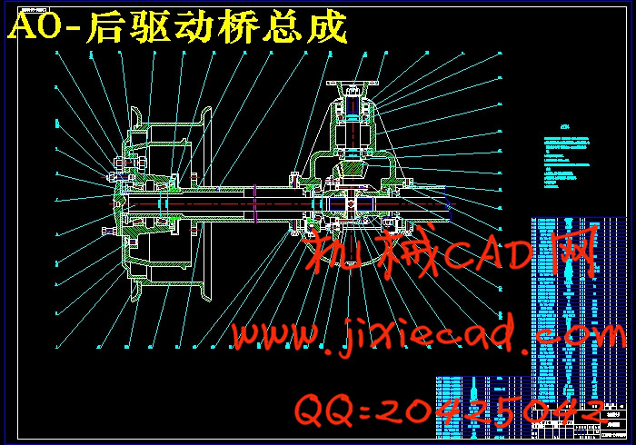
本次设计确定采用整体式驱动桥。其主减速器为单级,采用准双曲面齿轮传动,差速器采用普通对称式圆锥齿轮对称式圆差速器,全浮式半轴,整体铸造式驱动桥壳。主减速器齿轮主要设计的是双曲面齿轮的尺寸、校核及材料选择;差速器主要计算的是对称式圆锥齿轮的主要参数计算及校核;半轴设计主要是根据强度来确定半轴的半径和半轴的结构设计及材料与热处理;驱动桥桥壳既是承载件又是传动件,因此桥壳需要有足够的强度和刚度。
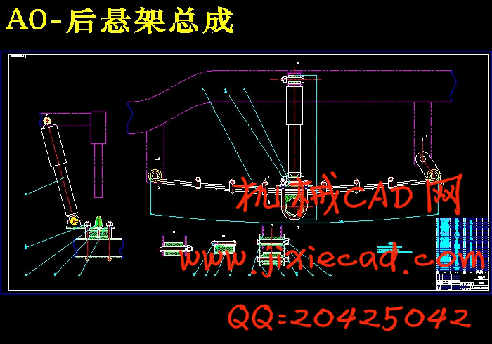
后悬架采用钢板弹簧式非独立悬架,其需要计算的内容比较广泛,但也主要是集中在对弹性元件的计算上。计算包含了从满载弧高,各钢板弹簧片长度、厚度、宽度,到整个悬架系统的动、静挠度值的确定。这是因为在悬架系统中,钢板弹簧既是它的弹性元件又是它的导向机构,是其最为重要的部件。
综合各部分的设计与校核的结果,本次设计基本能满足其设计要求。
关键词:后驱动桥, 整体式,非独立悬架,钢板弹簧
THE DESIGNING FOR THE MINIATURE MOTORCAR TO CARRY PERSONS AND GOODS WITH 4 SEATS
(THE DESIGN OF BACK DRIVING AXLE AND REAR SUSPENSION)
ABSTRACT
This design is for the back driving axle and back suspension of the miniature motorcar to carry persons and goods with 4 seats. According to the existing production technique level, synthesize the consideration production cost, and use the condition etc. various factor. In weeks , there was much useful information about the back driving axle and the rear suspension collected. With the helping of my teacher ,and observation on vehicle in laboratory , this designing is completed.
This design assurance adopts the whole type to drive the bridge. Its lord decelerates the machine as single class, the adoption allows a curved face wheel gear to spread to move, differ soon the machine adopt the common and symmetry type cone wheel gear symmetry type circle differ soon machine, the whole float type half stalk, hurtle to cast the whole type to drive the bridge hull. The lord mainly decelerate the machine wheel gear what to design is a pair of pit and the material choice of size, school of curved faces wheel gear. Bad soon machine mainly what to compute is the main parameter calculation and school pits of the symmetry type cone wheel gear.The half stalk design is mainly the basis strength to certain structure design and material and hot processingses of the radius and half stalk of the half stalks. Drive the bridge bridge hull since is to load the piece and is to spread to move the piece, so the bridge hull needs to have the enough strength and just degree.
The design of the rear suspension adopts unindependent suspension with steeel spring. It has more data computation.There are entire rate of rear suspension, heavy load arch high ,dynamic distortion quantity,the different length of different leaf brade, thickness and width of them.Those are indispensable data in suspension of a vehicle.
The result of design and school pit of comprehensive each part, this time design basic can satisfy it designs the request.
KEY WORDS:back driving axle, the whole type, unindependent suspension,steeel spring
目 录
第一章 前言............. ...................... ........1
第二章 驱动桥结构设计.................................2
§2.1驱动桥的组成与结构方案分析......................2
§2.2 主减速器的结构形式的分析和确定..................2
§2.2.1 主减速器传动齿轮的类型......................2
§2.2.2 主减速器的减速形式..........................3
§2.3差速器的方案分析及确定......................... .3
§2.4半轴............................................3
§2. 5驱动桥壳结构方案分析............................4
第三章 驱动桥尺寸计算 .................................5
§3.1主减速器的基本参数选择与设计计算................5
§3.1.1主减速比 的确定.............................5
§3.1.2主减速器齿轮计算载荷的确定.................. 5
§3.1.3主减速器齿轮基本参数的选择.................. 6
§3.2差速器的基本参数选择与设计计算.................17
§3.2.1差速器齿轮的基本参数的选择................. 17
§3.2.2差速器齿轮的几何尺寸设计计算............... 18
§3.3全浮式半轴的设计计算...........................20
§3.4驱动桥桥壳的设计计算...........................21
§3.4.1驱动桥壳结构方案分析....................... 21
§3.4.2驱动桥壳强度计算........................... 22
第四章 驱动桥强度计算.................................28
§4.1主减速器准双曲面齿轮的强度校核.................28
§4.1.1单位齿长圆周力............................. 28
§4.1.2轮齿的弯曲强度计算 ........................29
§4.1.3轮齿的弯曲强度计算......................... 30
§4.2差速器齿轮的强度计算...........................30
§4.3半轴强度计算...................................31
§4.3.1半轴扭转应力............................... 31
§4.3.2半轴的最大扭转角........................... 31
第五章 轴承的寿命计算.................................33
§5.1主减速器主动锥齿轮支承轴承的计算...............33
§5.1.1主减速器主动齿轮上的当量转矩 的计算....... 33
§5.1.2主从动锥齿轮齿面宽中点处的圆周力p的计算....33
§5.1.3双曲面齿轮的轴向力与径向力的计算........... 33
§5.1.4悬臂式支承主动锥齿轮的轴承径向载荷的确定... 34
§5.1.5轴承寿命的计算............................. 35
§5.2从动齿轮支承轴承校核...........................36
§5.2.1单级主减速器从动齿轮支承轴承径向载荷的确定. 36
§5.2.2轴承寿命计算............................... 36
第六章 后悬架结构分析.................................38
§6.1悬架概述.......................................38
§6.2悬架结构形式和布置的分析.......................38
第七章 后悬架参数确定和尺寸计算.......................40
§7.1总体布置及其基本参数...........................40
§7.2弹性元件的设计计算.............................40
§7.2.1钢板弹簧的布置方案......................... 40
§7.2.2钢板弹簧结构尺寸参数计算................... 40
§7.3后悬架减振器的设计与计算....................... 47
§7.3.1选取相对阻尼系数 ..........................47
§7.3.2最大卸荷力 的确定..........................47
§7.3.3减振器工作缸直径D的确定....................47
第八章 结 论..........................................48
参考文献...............................................49
致谢...................................................50
(后驱动桥、后悬设计)
摘 要
本设计为4座微型客货两用车的后驱动桥、后悬架设计。参照现有的生产技术水平,综合考虑生产成本,以及使用条件等多种因素, 经过收集各类型的后驱动桥、悬架的资料、实车观测和老师的指导,完成了本次设计。
本次设计确定采用整体式驱动桥。其主减速器为单级,采用准双曲面齿轮传动,差速器采用普通对称式圆锥齿轮对称式圆差速器,全浮式半轴,整体铸造式驱动桥壳。主减速器齿轮主要设计的是双曲面齿轮的尺寸、校核及材料选择;差速器主要计算的是对称式圆锥齿轮的主要参数计算及校核;半轴设计主要是根据强度来确定半轴的半径和半轴的结构设计及材料与热处理;驱动桥桥壳既是承载件又是传动件,因此桥壳需要有足够的强度和刚度。
后悬架采用钢板弹簧式非独立悬架,其需要计算的内容比较广泛,但也主要是集中在对弹性元件的计算上。计算包含了从满载弧高,各钢板弹簧片长度、厚度、宽度,到整个悬架系统的动、静挠度值的确定。这是因为在悬架系统中,钢板弹簧既是它的弹性元件又是它的导向机构,是其最为重要的部件。
综合各部分的设计与校核的结果,本次设计基本能满足其设计要求。
关键词:后驱动桥, 整体式,非独立悬架,钢板弹簧
THE DESIGNING FOR THE MINIATURE MOTORCAR TO CARRY PERSONS AND GOODS WITH 4 SEATS
(THE DESIGN OF BACK DRIVING AXLE AND REAR SUSPENSION)
ABSTRACT
This design is for the back driving axle and back suspension of the miniature motorcar to carry persons and goods with 4 seats. According to the existing production technique level, synthesize the consideration production cost, and use the condition etc. various factor. In weeks , there was much useful information about the back driving axle and the rear suspension collected. With the helping of my teacher ,and observation on vehicle in laboratory , this designing is completed.
This design assurance adopts the whole type to drive the bridge. Its lord decelerates the machine as single class, the adoption allows a curved face wheel gear to spread to move, differ soon the machine adopt the common and symmetry type cone wheel gear symmetry type circle differ soon machine, the whole float type half stalk, hurtle to cast the whole type to drive the bridge hull. The lord mainly decelerate the machine wheel gear what to design is a pair of pit and the material choice of size, school of curved faces wheel gear. Bad soon machine mainly what to compute is the main parameter calculation and school pits of the symmetry type cone wheel gear.The half stalk design is mainly the basis strength to certain structure design and material and hot processingses of the radius and half stalk of the half stalks. Drive the bridge bridge hull since is to load the piece and is to spread to move the piece, so the bridge hull needs to have the enough strength and just degree.
The design of the rear suspension adopts unindependent suspension with steeel spring. It has more data computation.There are entire rate of rear suspension, heavy load arch high ,dynamic distortion quantity,the different length of different leaf brade, thickness and width of them.Those are indispensable data in suspension of a vehicle.
The result of design and school pit of comprehensive each part, this time design basic can satisfy it designs the request.
KEY WORDS:back driving axle, the whole type, unindependent suspension,steeel spring
目 录
第一章 前言............. ...................... ........1
第二章 驱动桥结构设计.................................2
§2.1驱动桥的组成与结构方案分析......................2
§2.2 主减速器的结构形式的分析和确定..................2
§2.2.1 主减速器传动齿轮的类型......................2
§2.2.2 主减速器的减速形式..........................3
§2.3差速器的方案分析及确定......................... .3
§2.4半轴............................................3
§2. 5驱动桥壳结构方案分析............................4
第三章 驱动桥尺寸计算 .................................5
§3.1主减速器的基本参数选择与设计计算................5
§3.1.1主减速比
§3.1.2主减速器齿轮计算载荷的确定.................. 5
§3.1.3主减速器齿轮基本参数的选择.................. 6
§3.2差速器的基本参数选择与设计计算.................17
§3.2.1差速器齿轮的基本参数的选择................. 17
§3.2.2差速器齿轮的几何尺寸设计计算............... 18
§3.3全浮式半轴的设计计算...........................20
§3.4驱动桥桥壳的设计计算...........................21
§3.4.1驱动桥壳结构方案分析....................... 21
§3.4.2驱动桥壳强度计算........................... 22
第四章 驱动桥强度计算.................................28
§4.1主减速器准双曲面齿轮的强度校核.................28
§4.1.1单位齿长圆周力............................. 28
§4.1.2轮齿的弯曲强度计算 ........................29
§4.1.3轮齿的弯曲强度计算......................... 30
§4.2差速器齿轮的强度计算...........................30
§4.3半轴强度计算...................................31
§4.3.1半轴扭转应力............................... 31
§4.3.2半轴的最大扭转角........................... 31
第五章 轴承的寿命计算.................................33
§5.1主减速器主动锥齿轮支承轴承的计算...............33
§5.1.1主减速器主动齿轮上的当量转矩
§5.1.2主从动锥齿轮齿面宽中点处的圆周力p的计算....33
§5.1.3双曲面齿轮的轴向力与径向力的计算........... 33
§5.1.4悬臂式支承主动锥齿轮的轴承径向载荷的确定... 34
§5.1.5轴承寿命的计算............................. 35
§5.2从动齿轮支承轴承校核...........................36
§5.2.1单级主减速器从动齿轮支承轴承径向载荷的确定. 36
§5.2.2轴承寿命计算............................... 36
第六章 后悬架结构分析.................................38
§6.1悬架概述.......................................38
§6.2悬架结构形式和布置的分析.......................38
第七章 后悬架参数确定和尺寸计算.......................40
§7.1总体布置及其基本参数...........................40
§7.2弹性元件的设计计算.............................40
§7.2.1钢板弹簧的布置方案......................... 40
§7.2.2钢板弹簧结构尺寸参数计算................... 40
§7.3后悬架减振器的设计与计算....................... 47
§7.3.1选取相对阻尼系数
§7.3.2最大卸荷力
§7.3.3减振器工作缸直径D的确定....................47
第八章 结 论..........................................48
参考文献...............................................49
致谢...................................................50


