设计简介
摘 要
随着当今工业设备对精密程度的要求越来越高,加工设备的机械加工设备的加工的精密程度也要求越来越高。在搜索、查阅研究大量有关资料的基础上,对机床自动化技术进行了深入的研究和分析,并描述了机床控制系统的设计。整个过程主要对CA6140车床主传动进行设计。
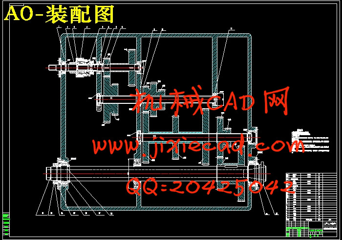
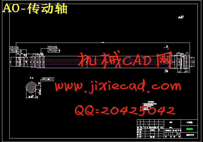
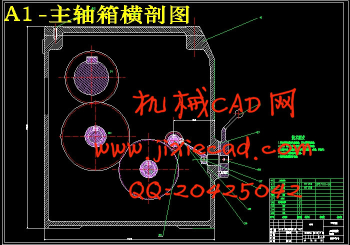
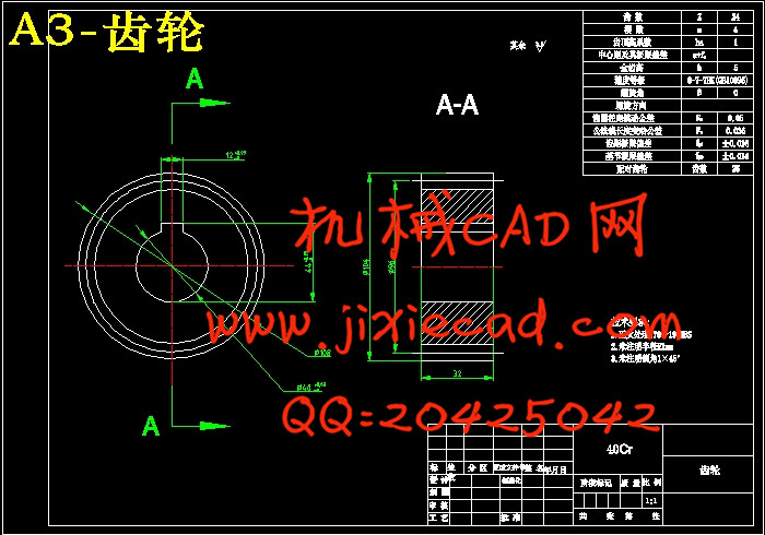
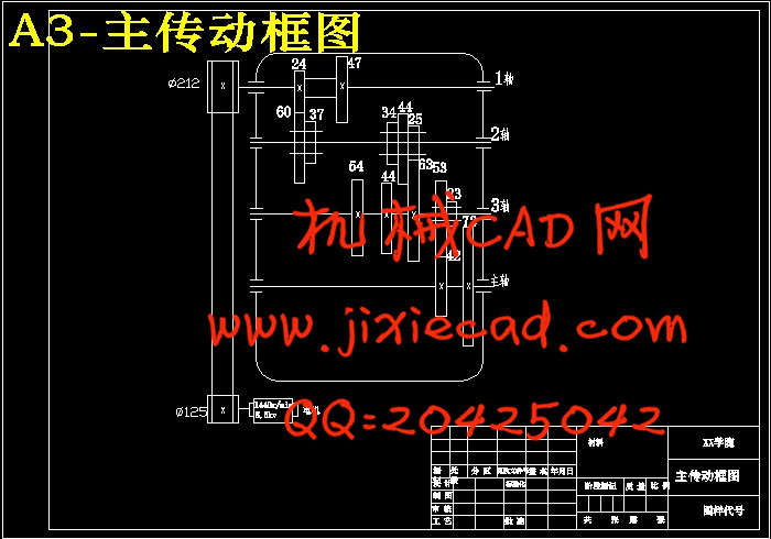
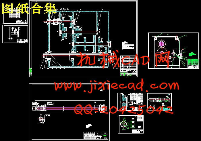
CA6140车床主传动设计,主要包括三方面的设计,即:根据设计题目所给定的机床用途、规格、主轴极限转速、转速数列公比或级数,确定其他有关运动参数,选定主轴各级转速值;通过分析比较,选择传动方案;拟定结构式或结构网,拟定转速图;确定齿轮齿数及带轮直径;绘制传动系统图。其次,根据机床类型和电动机功率,确定主轴及各传动件的计算转速,初定传动轴直径、齿轮模数,确定传动带型号及根数,摩擦片尺寸及数目;装配草图完成后要验算传动件(传动轴、主轴、齿轮、滚动轴承)的刚度、强度或寿命。最后,完成运动设计和动力设计后,要将主传动方案“结构化”,设计主轴变速箱装配图及零件图,侧重进行传动轴组件、主轴组件、变速机构、箱体、润滑与密封、传动轴及滑移齿轮零件的设计。
关键词:CA6140车床;数控;传动系统
Abstract
With the industrial equipment for precision degree of the increasingly high demand, the degree of precision machining processing equipment of machining equipment also to request more and more high. In the search, a lot of related data access research of machine tool automation technology, in-depth research and analysis, and describes the design of machine tool control system. The whole process is mainly carries on the design to the main drive lathe.CNC lathe main drive design, including the design, three aspects: according to the design of machine tool use, the given specifications, spindle speed limit, speed ratio determined sequence or series, other relevant motion parameters, selected at speed of the main shaft; through analysis and comparison, select the transmission scheme; develop structure or structure, develop speed diagram; to determine the number of gear teeth and belt pulley diameter; drawing drive system diagram. Secondly, based on the machine type and motor power, determining the spindle and the transmission of the computation speed, initial drive shaft diameter, the gear modulus, determine the transmission belt type and number of roots, friction plate size and number of assembly drawing; after checking transmission parts (gear, shaft, shaft, bearing stiffness,) strength or fatigue life. Finally, to complete the exercise design and dynamic design, to the main transmission scheme "structured", design of spindle gearbox assembly drawing and parts drawing, focuses on the transmission shaft assembly, spindle assembly, transmission mechanism, box, lubrication and seal, the transmission shaft and the sliding gear parts design.
Key words:lathe; CNC; transmission system
目 录
摘 要 IAbstract II
目 录 III
1 绪 论 1
1.1 数控技术的应用与发展 1
1.1.1数控机床与发展趋势 1
1.1.2数控技术 2
1.1.3数控技术发展趋势 4
1.1.4数控技术在机械工业中的进展 6
1.2数控CA6140车床的工艺范围及加工精度 7
1.2.1工艺范围 7
1.2.2加工精度 7
1.3本文的选题及主要研究内容 8
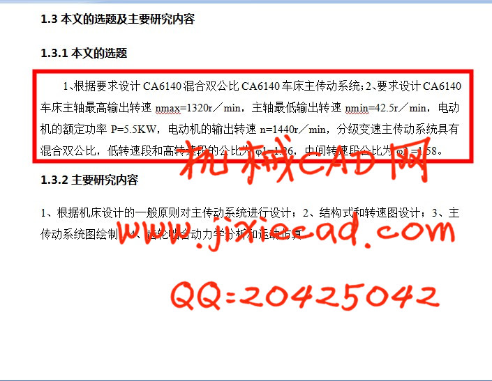
1.3.1本文的选题 8
1.3.2主要研究内容 8
2 主传动系统参数计算 9
2.1CA6140车床主参数和基本参数 9
2.2拟定参数的步骤和方法 9
2.2.1 极限切削速度Vmax、Vmin 9
2.2.2 主轴的极限转速 10
2.2.3 主电机功率——动力参数的确定 10
2.2.4确定结构式 11
2.2.5确定结构网 11
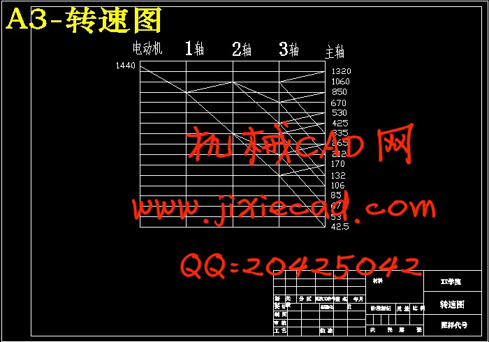
2.2.6绘制转速图和传动系统图 11
2.3 确定各变速组此论传动副齿数 12
3 传动件的设计 13
3.1 带轮的设计 13
3.2 传动轴的直径估算 15
3.2.1 确定各轴转速 16
3.2.2传动轴直径的估算:确定各轴最小直径 16
3.2.3 键的选择 17
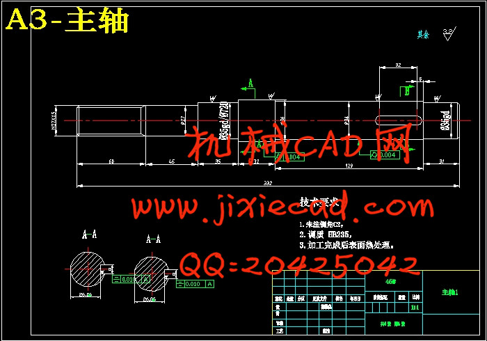
3.3 传动轴的校核 17
3.3.1 传动轴的校核 18
3.3.2 键的校核 18
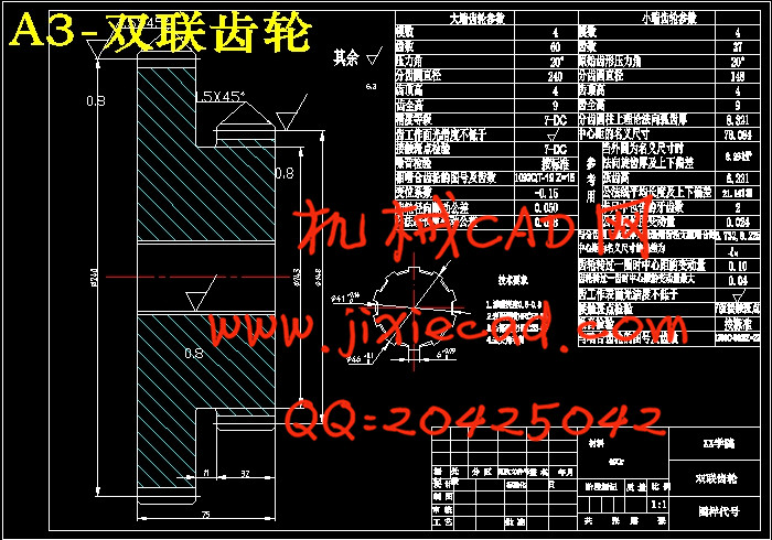
3.4 各变速组齿轮模数的确定和校核 19
3.4.1 齿轮模数的确定: 19
3.4.2 齿宽的确定 23
3.4.3 齿轮结构的设计 24
3.5 带轮结构设计 24
3.6 片式摩擦离合器的选择和计算 25
3.7 齿轮校验 28
3.7.1 校核I组变速组齿轮 28
3.7.2 校核II组变速组齿轮 29
3.7.3 校核III组变速组齿轮 31
3.8 轴承的选用与校核 32
3.8.1 各轴轴承的选用 32
3.8.2 各轴轴承的校核 32
总结与展望 35
参考文献 36
致 谢 37